Lexus NX: Communication Malfunction (Bus Ic) (B1497)
DESCRIPTION
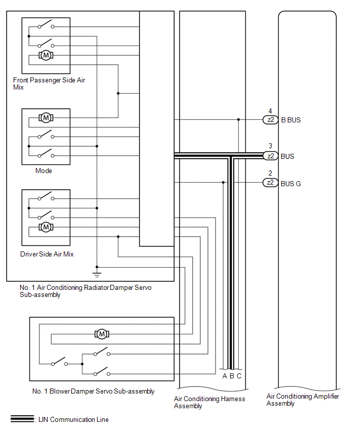
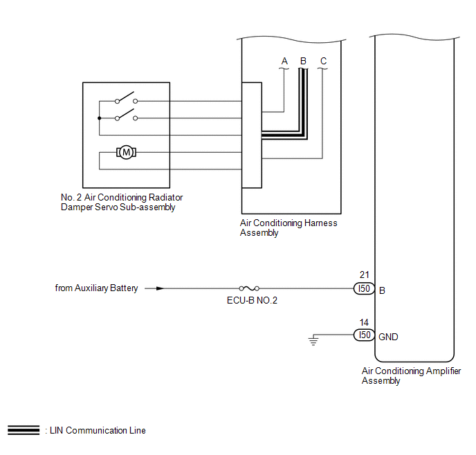
The air conditioning harness assembly connects the air conditioning amplifier assembly and the servo motors. The air conditioning amplifier assembly supplies power and sends operation instructions to each servo motor through the air conditioning harness assembly. Each servo motor sends damper position information to the air conditioning amplifier assembly.
| DTC No. | Detection Item | DTC Detection Condition | Trouble Area | Memory | Note |
|---|---|---|---|---|---|
| B1497 | Communication Malfunction (Bus Ic) | Error or open in communication line |
| Memorized (10 seconds or more) | - |
HINT:
The air conditioning amplifier assembly stores the DTC of the respective malfunction if it has occurred for the period of time indicated in the brackets.
WIRING DIAGRAM
CAUTION / NOTICE / HINT
NOTICE:
- Inspect the fuses for circuits related to this system before performing the following procedure.
-
When the auxiliary battery is disconnected or the air conditioning amplifier assembly is replaced, be sure to perform servo motor initialization.
Click here
.gif)
PROCEDURE
| 1. | CHECK FOR DTC |
(a) Clear the DTC.
Click here
(b) Check for DTC.
Click here
| Result | Proceed to |
|---|---|
| DTC B1497 is not output | A |
| DTC B1497 is output | B |
| A | .gif) | USE SIMULATION METHOD TO CHECK |
|
.gif)
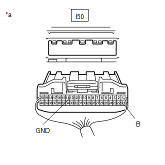
| 2. | CHECK HARNESS AND CONNECTOR (AIR CONDITIONING AMPLIFIER ASSEMBLY - BATTERY AND BODY GROUND) |
| (a) Disconnect the air conditioning amplifier assembly connectors. |
|
(b) Measure the voltage according to the value(s) in the table below.
Standard Voltage:
| Tester Connection | Switch Condition | Specified Condition |
|---|---|---|
| I50-21 (B) - Body ground | Power switch off | 11 to 14 V |
(c) Measure the resistance according to the value(s) in the table below.
Standard Resistance:
| Tester Connection | Condition | Specified Condition |
|---|---|---|
| I50-14 (GND) - Body ground | Always | Below 1 Ω |
| NG | | REPAIR OR REPLACE HARNESS OR CONNECTOR |
|
| 3. | PERFORM ACTIVE TEST USING TECHSTREAM |
(a) Connect the Techstream to the DLC3.
(b) Turn the power switch on (IG).
(c) Turn the Techstream on.
(d) Enter the following menus: Body Electrical / Air Conditioner / Active Test.
(e) Check the operation by referring to the table below.
Body Electrical > Air Conditioner > Active Test| Tester Display | Measurement Item | Control Range | Diagnostic Note |
|---|---|---|---|
| Air Mix Servo Targ Pulse(D) | No. 1 air conditioning radiator damper servo sub-assembly (driver side air mix) pulse | Min.: 128 Max.: 383 | Operates between 165 and 257 pulse |
| Air Mix Servo Targ Pulse(P) | No. 1 air conditioning radiator damper servo sub-assembly (front passenger side air mix) pulse | Min.: 128 Max.: 383 | Operates between 255 and 347 pulse |
| Air Outlet Servo Pulse (D) | No. 1 air conditioning radiator damper servo sub-assembly (mode) pulse | Min.: 128 Max.: 383 | Operates between 256 and 348 pulses |
| Air Inlet Damper Targ Pulse | No. 1 blower damper servo sub-assembly target pulse | Min.: 128 Max.: 383 | Operates between 235 and 258 pulses |
| A/O Servo Pulse(Rr D) | No. 2 air conditioning radiator damper servo sub-assembly target pulse | Min.: 128 Max.: 383 | Operates between 166 and 264 pulses |
| Tester Display |
|---|
| Air Mix Servo Targ Pulse(D) |
| Tester Display |
|---|
| Air Mix Servo Targ Pulse(P) |
| Tester Display |
|---|
| Air Outlet Servo Pulse (D) |
| Tester Display |
|---|
| Air Inlet Damper Targ Pulse |
| Tester Display |
|---|
| A/O Servo Pulse(Rr D) |
OK:
Arm of the damper servo motor selected in the Active Test moves smoothly.
(f) According to the test result, proceed to the next step.
| Result | Proceed to |
|---|---|
| No. 1 air conditioning radiator damper servo sub-assembly (driver side air mix) is malfunctioning | A |
| No. 1 air conditioning radiator damper servo sub-assembly (front passenger side air mix) is malfunctioning | |
| No. 1 air conditioning radiator damper servo sub-assembly (mode) is malfunctioning | |
| No. 1 blower damper servo sub-assembly is malfunctioning | B |
| No. 2 air conditioning radiator damper servo sub-assembly is malfunctioning | C |
| B | | GO TO STEP 6 |
| C | | GO TO STEP 7 |
|
| 4. | CHECK NO. 1 AIR CONDITIONING RADIATOR DAMPER SERVO SUB-ASSEMBLY |
(a) Replace the No. 1 air conditioning radiator damper servo sub-assembly.
Click here
HINT:
Since the servo motor cannot be inspected while it is removed from the vehicle, replace the servo motor with a new or known good one and check that the condition returns to normal.
(b) Clear the DTC.
Click here
(c) Check for DTC.
Click here
| Result | Proceed to |
|---|---|
| DTC B1497 is not output | A |
| DTC B1497 is output | B |
| A | | END (NO. 1 AIR CONDITIONING RADIATOR DAMPER SERVO SUB-ASSEMBLY IS DEFECTIVE) |
|
| 5. | CHECK AIR CONDITIONING HARNESS ASSEMBLY |
(a) Replace the air conditioning harness assembly.
Click here
HINT:
Since the air conditioning harness assembly cannot be inspected while it is removed from the vehicle, replace the air conditioning harness assembly with a new or known good one and check that the condition returns to normal.
(b) Clear the DTC.
Click here
(c) Check for DTC.
Click here
| Result | Proceed to |
|---|---|
| DTC B1497 is not output | A |
| DTC B1497 is output | B |
| A | | END (AIR CONDITIONING HARNESS ASSEMBLY IS DEFECTIVE) |
| B | | REPLACE AIR CONDITIONING HARNESS ASSEMBLY |
| 6. | CHECK NO. 1 BLOWER DAMPER SERVO SUB-ASSEMBLY |
(a) Replace the No. 1 blower damper servo sub-assembly.
Click here
HINT:
Since the servo motor cannot be inspected while it is removed from the vehicle, replace the servo motor with a new or known good one and check that the condition returns to normal.
(b) Clear the DTC.
Click here
(c) Check for DTC.
Click here
| Result | Proceed to |
|---|---|
| DTC B1497 is not output | A |
| DTC B1497 is output | B |
| A | | END (NO. 1 BLOWER DAMPER SERVO SUB-ASSEMBLY IS DEFECTIVE) |
| B | | GO TO STEP 5 |
| 7. | CHECK NO. 2 AIR CONDITIONING RADIATOR DAMPER SERVO SUB-ASSEMBLY |
(a) Replace the No. 2 air conditioning radiator damper servo sub-assembly.
Click here
HINT:
Since the servo motor cannot be inspected while it is removed from the vehicle, replace the servo motor with a new or known good one and check that the condition returns to normal.
(b) Clear the DTC.
Click here
(c) Check for DTC.
Click here
| Result | Proceed to |
|---|---|
| DTC B1497 is not output | A |
| DTC B1497 is output | B |
| A | | END (NO. 2 AIR CONDITIONING RADIATOR DAMPER SERVO SUB-ASSEMBLY IS DEFECTIVE) |
| B | | GO TO STEP 5 |
READ NEXT:
 Communication Malfunction (A/C Inverter Local) (B1498)
DESCRIPTION The hybrid vehicle control ECU and compressor with motor assembly communicate via a direct line. Compressor control is stopped and this DTC is stored if communication information is cut of
Glass Temperature Sensor Circuit (B14A8)
DESCRIPTION The air conditioning amplifier assembly detects the windshield glass surface temperature from this circuit. The air conditioning amplifier assembly applies voltage to the air conditioning
Glass Surroundings Temperature Sensor Circuit (B14A9)
DESCRIPTION The air conditioning amplifier assembly detects the temperature of the area near the windshield glass using this circuit. The air conditioning amplifier assembly applies voltage to the air
SEE MORE:
Hazard Warning Switch
InspectionINSPECTION PROCEDURE 1. INSPECT AIR CONDITIONING CONTROL ASSEMBLY (HAZARD WARNING SWITCH) (a) Remove the air conditioning control assembly. Click here (b) Inspect the hazard warning switch. (1) Measure the resistance according to the value(s) in the table below. Standard Resistance:
Master Cylinder Pressure Sensor (C1246,C1281,C1364)
DESCRIPTION The regulator pressure sensor and wheel cylinder pressure sensor are built into the brake actuator. They measure their respective pressures and send signals to the skid control ECU (brake booster with master cylinder assembly). DTC C1281 will be cleared when the regulator pressure sensor
