Lexus NX: Installation
INSTALLATION
PROCEDURE
1. INSTALL TRANSMISSION OIL COOLER ASSEMBLY
| (a) Insert the stud bolts E through the transmission oil cooler assembly. |
|
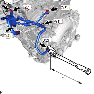
(b) Temporarily install the transmission oil cooler assembly and a new gasket with the flare nut B and union bolt C.
(c) Temporarily install the No. 1 oil cooler tube clamp with the bolt A.
(d) Tighten the 2 bolts, 2 nuts, union bolt and flare nut in the sequence shown in the illustration.
Torque:
Bolt A :
8.2 N·m {84 kgf·cm, 73 in·lbf}
Flare nut B :
34.3 N·m {350 kgf·cm, 25 ft·lbf}
Union bolt C :
35 N·m {357 kgf·cm, 26 ft·lbf}
Bolt D :
5.5 N·m {56 kgf·cm, 49 in·lbf}
Nut E :
5.5 N·m {56 kgf·cm, 49 in·lbf}
HINT:
-
Calculate the torque wrench reading when changing the fulcrum length of the torque wrench.
Click here
.gif)
- When using a union nut wrench (fulcrum length of 30 mm (1.1811 in.)) + torque wrench (fulcrum length of 180 mm (7.0866 in.)): 29.4 N*m (300 kgf*cm, 22 ft.*lbf)
| (e) Connect the transmission oil cooler assembly to the hybrid vehicle transaxle assembly, and slide the hose clamp to secure it. HINT: Install the transmission oil cooler assembly with the marking toward the bottom of the vehicle. |
|
2. CONNECT NO. 5 INVERTER COOLING HOSE
Click here
3. CONNECT TRANSMISSION CONTROL CABLE ASSEMBLY
Click here
4. CONNECT WIRE HARNESS
(a) Connect the 4 clamps, 2 connectors and wire harness to the hybrid vehicle transaxle assembly.
5. INSTALL INVERTER BRACKET ASSEMBLY
Click here
6. INSTALL INVERTER WATER PUMP WITH MOTOR ASSEMBLY
Click here
7. INSTALL INVERTER WITH CONVERTER ASSEMBLY
Click here
8. INSTALL NO. 1 ENGINE UNDER COVER ASSEMBLY
Click here
9. ADD HYBRID TRANSAXLE FLUID
Click here
10. INSPECT HYBRID TRANSAXLE FLUID
Click here
READ NEXT:
 Components
COMPONENTS ILLUSTRATION *1 SHIFT LEVER ASSEMBLY *2 SHIFT LEVER CAP *3 SHIFT POSITION INDICATOR *4 SHIFTING HOLE COVER SUB-ASSEMBLY *5 TRANSMISSION CONTROL CABLE ASSEMBLY *6
On-vehicle Inspection
ON-VEHICLE INSPECTION PROCEDURE 1. INSPECT SHIFT LEVER ASSEMBLY (a) Inspect shift lock operation. (1) Move the shift lever to P. (2) Turn the power switch off. (3) Check that the shift lever cannot be
SEE MORE:
Dcm Operation History
DCM OPERATION HISTORY HINT:
This function shows the telematics network status when the DCM (telematics transceiver) was operated. Use this when no DTC is present but this telematics system was unable to connect to the call center. This symptom may occur if cell phone signal strength is very weak.
Fuel Receiver Gauge Display Malfunction
DESCRIPTION OPERATION The combination meter assembly uses the fuel injection volume signal from the ECM, fuel sender gauge assembly to detect the amount of fuel remaining in the fuel tank assembly. Each gauge assembly has a variable resistor whose resistance changes according to the amount of fuel r
