Lexus NX: Components
Lexus NX Service Manual / Drivetrain / P314 (hybrid Transmission / Transaxle) / Shift Lever / Components
COMPONENTS
ILLUSTRATION
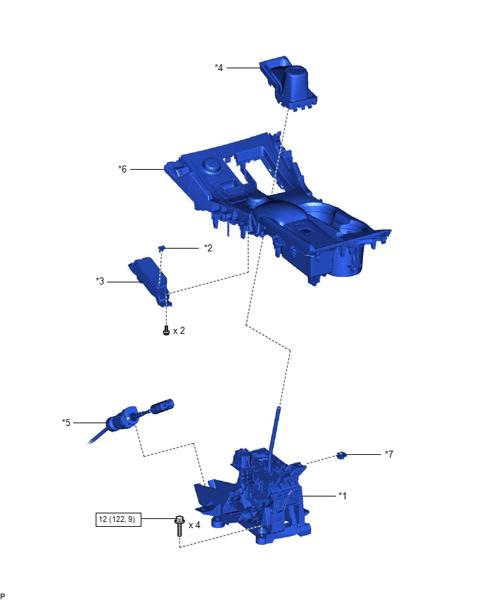
| *1 | SHIFT LEVER ASSEMBLY | *2 | SHIFT LEVER CAP |
| *3 | SHIFT POSITION INDICATOR | *4 | SHIFTING HOLE COVER SUB-ASSEMBLY |
| *5 | TRANSMISSION CONTROL CABLE ASSEMBLY | *6 | REAR UPPER CONSOLE PANEL SUB-ASSEMBLY |
| *7 | NUT | - | - |
.png) | N*m (kgf*cm, ft.*lbf): Specified torque | - | - |
READ NEXT:
 On-vehicle Inspection
ON-VEHICLE INSPECTION PROCEDURE 1. INSPECT SHIFT LEVER ASSEMBLY (a) Inspect shift lock operation. (1) Move the shift lever to P. (2) Turn the power switch off. (3) Check that the shift lever cannot be
Removal
REMOVAL PROCEDURE 1. REMOVE NO. 1 SPEAKER WITH BOX ASSEMBLY (w/ ASC System) Click here 2. REMOVE REAR CONSOLE BOX ASSEMBLY (w/o ASC System) Click here 3. DISCONNECT TRANSMISSION CONTROL CABLE ASS
Disassembly
DISASSEMBLY PROCEDURE 1. REMOVE SHIFT LEVER CAP (a) Using a screwdriver with its tip wrapped with protective tape, detach the 2 claws and remove the shift lever cap from the shift position indicato
SEE MORE:
Head restraints
Head restraints are provided for all
seats.
WARNING
■Head restraint precautions
Observe the following precautions
regarding the head restraints.
Failure to do so may result in death or
serious injury.
Use the head restraints designed for
each respective seat.
Adjust the head restr
Installation
INSTALLATION PROCEDURE 1. INSTALL THEFT WARNING ULTRASONIC SENSOR (a) Attach the 4 clamps to install the theft warning ultrasonic sensor. (b) Install the 6 screws and connect the connector. 2. INSTALL MAP LIGHT ASSEMBLY Click here 3. CONNECT CABLE TO NEGATIVE AUXILIARY BATTERY TERMINAL 4. INITIALI
© 2016-2026 Copyright www.lexunx.com
