Lexus NX: Terminals Of Ecm
TERMINALS OF ECM
HINT:
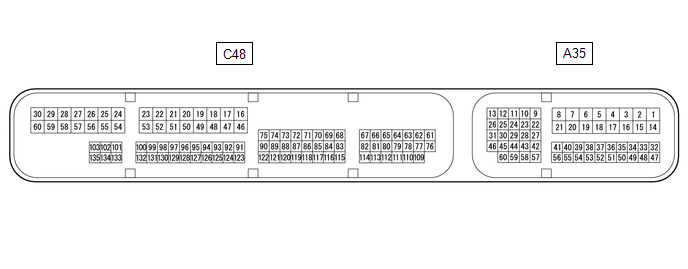
The standard voltage, resistance and waveform between each pair of the ECM terminals is shown in the table below. The appropriate conditions for checking each pair of the terminals is also indicated. The result of checks should be compared with the standard voltage, resistance and waveform for each pair of the terminals as displayed in the Specified Condition column. The illustration above can be used as a reference to identify the ECM terminal locations.
| Terminal No. (Symbol) | Wiring Color | Terminal Description | Condition | Specified Condition |
|---|---|---|---|---|
| A35-1 (BATT) - C48-16 (E1) | V - BR | Auxiliary battery (for measuring auxiliary battery voltage and for ECM memory) | Power switch off | 11 to 16 V |
| A35-2 (+B) - C48-16 (E1) | L - BR | Power source of ECM | Power switch on (IG) | 11 to 14 V |
| A35-3 (+B2) - C48-16 (E1) | L - BR | Power source of ECM | Power switch on (IG) | 11 to 14 V |
| C48-29 (+BM) - C48-16 (E1) | GR - BR | Power source of throttle actuator | Power switch off | 11 to 16 V |
| A35-46 (MREL) - C48-16 (E1) | P - BR | EFI-MAIN relay operation signal | Power switch on (IG) | 11 to 14 V |
| C48-113 (VCV1) - C48-16 (E1) | W - BR | Power source for camshaft position sensor (specific voltage) | Power switch on (IG) | 4.5 to 5.5 V |
| A35-37 (IGSW) - C48-16 (E1) | B - BR | Power switch signal | Power switch on (IG) | 11 to 14 V |
| C48-125 (VCTA) - C48-126 (ETA) | Y - L | Power source for throttle position sensor (specific voltage) | Power switch on (IG) | 4.5 to 5.5 V |
| C48-127 (VTA1) - C48-126 (ETA) | G - L | Throttle position sensor signal (for engine control) | Power switch on (IG), accelerator pedal fully released | 0.5 to 1.1 V |
| C48-128 (VTA2) - C48-126 (ETA) | R - L | Throttle position sensor signal (for sensor malfunction detection) | Power switch on (IG), accelerator pedal fully released | 2.1 to 3.1 V |
| A35-7 (VPMP) - C48-16 (E1) | B - BR | Vent valve (built into canister pump module) | Power switch on (IG) | 11 to 14 V |
| A35-19 (MPMP) - C48-16 (E1) | W - BR | Leak detection pump (built into canister pump module). | Leak detection pump off | Below 3.0 V |
| Leak detection pump on | 9 to 14 V | |||
| A35-49 (PPMP) - C48-16 (E1) | L - BR | Canister pressure sensor (built into canister pump module) | Power switch on (IG) | 3.0 to 3.6 V |
| A35-34 (VCPP) - A35-48 (EPPM) | V - G | Power source for canister pressure sensor (specific voltage) | Power switch on (IG) | 4.5 to 5.5 V |
| C48-20 (#10) - C48-50 (E01) | L - W-B | No. 1 fuel injector assembly signal | Power switch on (IG) | 11 to 14 V |
| Idling with warm engine | Pulse generation (see waveform 1) | |||
| C48-17 (#20) - C48-50 (E01) | G - W-B | No. 2 fuel injector assembly signal | Power switch on (IG) | 11 to 14 V |
| Idling with warm engine | Pulse generation (see waveform 1) | |||
| C48-18 (#30) - C48-50 (E01) | B - W-B | No. 3 fuel injector assembly signal | Power switch on (IG) | 11 to 14 V |
| Idling with warm engine | Pulse generation (see waveform 1) | |||
| C48-19 (#40) - C48-50 (E01) | W - W-B | No. 4 fuel injector assembly signal | Power switch on (IG) | 11 to 14 V |
| Idling with warm engine | Pulse generation (see waveform 1) | |||
| C48-74 (OC1+) - C48-75 (OC1-) | B - V | Camshaft timing oil control valve assembly operation signal | Idling | Pulse generation (see waveform 2) |
| C48-82 (VV1+) - C48-114 (VV1-) | B - R | Camshaft position sensor signal | Idling with warm engine | Pulse generation (see waveform 16) |
| C48-76 (NE+) - C48-109 (NE-) | W - B | Crankshaft position sensor signal | Idling with warm engine | Pulse generation (see waveform 3) |
| C48-60 (M+) - C48-58 (ME01) | V - W-B | Throttle actuator operation signal (positive terminal) | Idling with warm engine | Pulse generation (see waveform 5) |
| C48-30 (M-) - C48-58 (ME01) | P - W-B | Throttle actuator operation signal (negative terminal) | Idling with warm engine | Pulse generation (see waveform 6) |
| C48-57 (IGT1) - C48-16 (E1) | R - BR | No. 1 ignition coil assembly (ignition signal) | Idling with warm engine | Pulse generation (see waveform 7) |
| C48-56 (IGT2) - C48-16 (E1) | B - BR | No. 2 ignition coil assembly (ignition signal) | Idling with warm engine | Pulse generation (see waveform 7) |
| C48-55 (IGT3) - C48-16 (E1) | G - BR | No. 3 ignition coil assembly (ignition signal) | Idling with warm engine | Pulse generation (see waveform 7) |
| C48-54 (IGT4) - C48-16 (E1) | L - BR | No. 4 ignition coil assembly (ignition signal) | Idling with warm engine | Pulse generation (see waveform 7) |
| C48-51 (IGF1) - C48-16 (E1) | W - BR | Ignition coil assembly (ignition confirmation signal) | Power switch on (IG) | 4.5 to 5.5 V |
| Idling with warm engine | Pulse generation (see waveform 7) | |||
| C48-95 (THW) - C48-96 (ETHW) | GR - P | Engine coolant temperature sensor signal | Idling, engine coolant temperature 60 to 120°C (140 to 248°F) | 0.2 to 1.0 V |
| C48-93 (THA) - C48-94 (ETHA) | B - V | Intake air temperature sensor signal | Idling, intake air temperature 0 to 80°C (32 to 176°F) | 0.5 to 3.4 V |
| C48-91 (VG) - C48-92 (E2G) | Y - L | Mass air flow meter sub-assembly signal | Idling, shift lever in P or N, A/C switch off | 0.5 to 3.0 V |
| C48-68 (PRG) - C48-16 (E1) | V - BR | Purge VSV for EVAP system operation signal | Power switch on (IG) | 11 to 14 V |
| Idling with warm engine, under purge control | Pulse generation (see waveform 8) | |||
| C48-133 (A1A+) - C48-16 (E1) | L - BR | Air fuel ratio sensor (sensor 1) signal | Power switch on (IG) | 3.3 V* |
| C48-134 (A1A-) - C48-16 (E1) | Y - BR | Air fuel ratio sensor (sensor 1) signal | Power switch on (IG) | 2.9 V* |
| C48-23 (HA1A) - C48-53 (E04) | W - BR | Air fuel ratio sensor (sensor 1) heater operation signal | Idling | Pulse generation (see waveform 9) |
| Power switch on (IG) | 11 to 14 V | |||
| C48-100 (OX1B) - C48-132 (EX1B) | L - Y | Heated oxygen sensor (sensor 2) signal | Engine speed maintained at 2500 rpm for 2 minutes after warming up engine | Pulse generation (see waveform 10) |
| C48-24 (HT1B) - C48-53 (E04) | R - BR | Heated oxygen sensor (sensor 2) heater operation signal | Idling | Below 3.0 V |
| Power switch on (IG) | 11 to 14 V | |||
| C48-123 (KNK1) - C48-124 (EKNK) | R - G | Knock control sensor signal | Engine speed maintained at 2500 rpm after warming up engine | Pulse generation (see waveform 11) |
| A35-13 (CANH) - C48-16 (E1) | Y - BR | CAN communication line | Power switch on (IG) | Pulse generation (see waveform 12) |
| A35-26 (CANL) - C48-16 (E1) | W - BR | CAN communication line | Power switch on (IG) | Pulse generation (see waveform 13) |
| A35-12 (CANP) - C48-16 (E1) | R - BR | CAN communication line | Power switch on (IG) | Pulse generation (see waveform 12) |
| A35-25 (CANN) - C48-16 (E1) | W - BR | CAN communication line | Power switch on (IG) | Pulse generation (see waveform 13) |
| A35-44 (RFC) - C48-16 (E1) | B - BR | Cooling fan control signal | Power switch on (IG), A/C switch on (max cool) | Pulse generation (see waveform 14) |
| A35-60 (G2O) - C48-16 (E1) | B - BR | Inverter with converter assembly (camshaft revolution signal) | Idling with warm engine | Pulse generation (see waveform 4) |
| C48-59 (GE01) - C48-16 (E1) | B - BR | Shielded earth (ground) circuit of throttle actuator | Always | Below 1 Ω |
| A35-21 (FPC) - C48-16 (E1) | R - BR | Fuel pump control | Engine stopped, power switch on (IG) | Below 1.5 V |
| C48-28 (EGR1) - C48-16 (E1) | L - BR | EGR valve assembly signal | EGR valve operating | Pulse generation (see waveform 15) |
| C48-27 (EGR2) - C48-16 (E1) | G - BR | EGR valve assembly signal | EGR valve operating | Pulse generation (see waveform 15) |
| C48-26 (EGR3) - C48-16 (E1) | V - BR | EGR valve assembly signal | EGR valve operating | Pulse generation (see waveform 15) |
| C48-25 (EGR4) - C48-16 (E1) | R - BR | EGR valve assembly signal | EGR valve operating | Pulse generation (see waveform 15) |
| C48-78 (VCPM) - C48-80 (EPIM) | L - G | Power source of absolute pressure sensor | Power switch on (IG) | 4.75 to 5.25 V |
| C48-79 (PIM) - C48-80 (EPIM) | V - G | Manifold absolute pressure sensor signal | Power switch on (IG) | 3.0 to 5.0 V |
| A35-9 (PWMS) - C48-16 (E1) | GR - BR | Driving mode select switch (SPORT mode) | Power switch on (IG), driving mode select switch being turned and held at SPORT position (SPORT mode) | 0 to 1.5 V |
| Power switch on (IG) | 11 to 14 V | |||
| A35-43 (SPCN) - C48-16 (E1) | L - BR | Driving mode select switch (NORMAL mode) | Power switch on (IG), driving mode select switch being pushed and held (NORMAL mode) | 0 to 1.5 V |
| Power switch on (IG) | 11 to 14 V | |||
| A35-14 (EC) - Body ground | BR - - | Ground | Always | Below 1 Ω |
| C48-16 (E1) - Body ground | BR - - | Ground | Always | Below 1 Ω |
| C48-50 (E01) - Body ground | W-B - - | Ground | Always | Below 1 Ω |
| C48-49 (E02) - Body ground | W-B - - | Ground | Always | Below 1 Ω |
| C48-53 (E04) - Body ground | BR - - | Ground | Always | Below 1 Ω |
| C48-58 (ME01) - Body ground | W-B - - | Ground | Always | Below 1 Ω |
*: The ECM terminal voltage is constant regardless of the output voltage from the sensor.
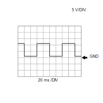
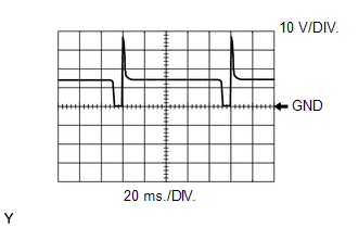
WAVEFORM 1
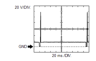 No. 1 (to No. 4) Fuel Injector Assembly Signal
 | ECM Terminal Name | Between #10 (to #40) and E01 |
| Tester Range | 20 V/DIV., 20 ms./DIV. |
| Condition | Idling with warm engine |
HINT:
The wavelength becomes shorter as the engine speed increases.
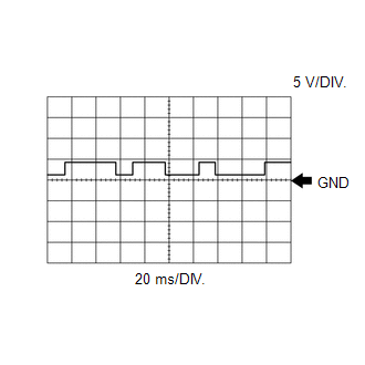
WAVEFORM 2
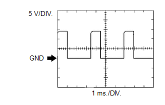 Camshaft Timing Oil Control Valve Assembly Operation Signal
 | ECM Terminal Name | Between OC1+ and OC1- |
| Tester Range | 5 V/DIV., 1 ms./DIV. |
| Condition | Idling |
WAVEFORM 3
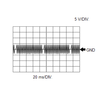 Crankshaft Position Sensor Signal
 | ECM Terminal Name | Between NE+ and NE- |
| Tester Range | 5 V/DIV., 20 ms./DIV. |
| Condition | Idling with warm engine |
HINT:
The wavelength becomes shorter as the engine speed increases.
WAVEFORM 4
 Camshaft Revolution Signal from Inverter with Converter Assembly
 | ECM Terminal Name | Between G2O and E1 |
| Tester Range | 5 V/DIV., 20 ms./DIV. |
| Condition | Idling with warm engine |
HINT:
The wavelength becomes shorter as the engine speed increases.
WAVEFORM 5
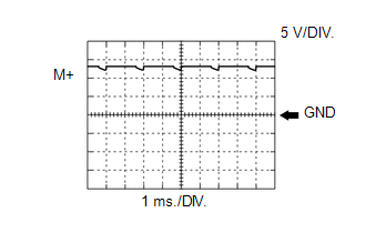 Throttle Actuator Positive Terminal Signal
 | ECM Terminal Name | Between M+ and ME01 |
| Tester Range | 5 V/DIV., 1 ms./DIV. |
| Condition | Idling with warm engine |
HINT:
The duty ratio varies depending on the throttle actuator operation.
WAVEFORM 6
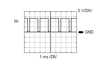 Throttle Actuator Negative Terminal Signal
 | ECM Terminal Name | Between M- and ME01 |
| Tester Range | 5 V/DIV., 1 ms./DIV. |
| Condition | Idling with warm engine |
HINT:
The duty ratio varies depending on the throttle actuator operation.
WAVEFORM 7
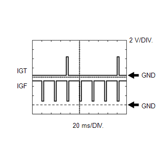 Ignition Coil Assembly Signal (IGT and IGF1 Signal)
 | ECM Terminal Name | Between IGT (1 to 4) and E1 Between IGF1 and E1 |
| Tester Range | 2 V/DIV., 20 ms./DIV. |
| Condition | Idling with warm engine |
HINT:
The wavelength becomes shorter as the engine speed increases.
WAVEFORM 8
 Purge VSV Operation Signal
 | ECM Terminal Name | Between PRG and E1 |
| Tester Range | 10 V/DIV., 20 ms./DIV. |
| Condition | Idling with warm engine, under purge control |
HINT:
If the waveform is not similar to the illustration, check the waveform again after idling for 10 minutes or more.
WAVEFORM 9
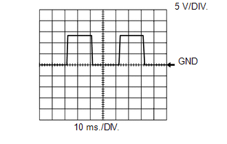 Air Fuel Ratio Sensor (Sensor 1) Heater Operation Signal
 | ECM Terminal Name | Between HA1A and E04 |
| Tester Range | 5 V/DIV., 10 ms./DIV. |
| Condition | Idling |
WAVEFORM 10
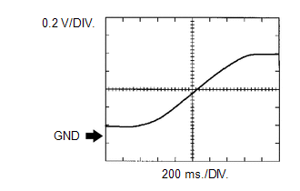 Heated Oxygen Sensor (Sensor 2) Signal
 | ECM Terminal Name | Between OX1B and EX1B |
| Tester Range | 0.2 V/DIV., 200 ms./DIV. |
| Condition | Engine speed maintained at 2500 rpm for 2 minutes after warming up engine |
HINT:
In the Data List, item O2S B1S2 shows the ECM values from the heated oxygen sensor.
WAVEFORM 11
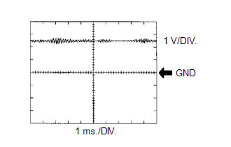 Knock Control Sensor Signal
 | ECM Terminal Name | Between KNK1 and EKNK |
| Tester Range | 1 V/DIV., 1 ms./DIV. |
| Condition | Engine speed maintained at 2500 rpm after warming up engine |
HINT:
- The wavelength becomes shorter as the engine speed increases.
- The waveforms and amplitudes displayed differ slightly depending on the vehicle condition.
WAVEFORM 12
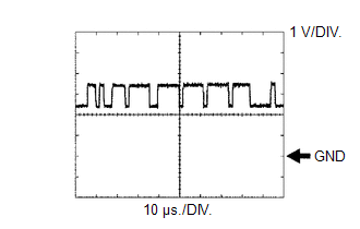 CAN Communication Signal (Reference)
 | ECM Terminal Name | Between CANH and E1, or CANP and E1 |
| Tester Range | 1 V/DIV., 10 μs./DIV. |
| Condition | Power switch on (IG) |
HINT:
The waveform varies depending on the CAN communication signal.
WAVEFORM 13
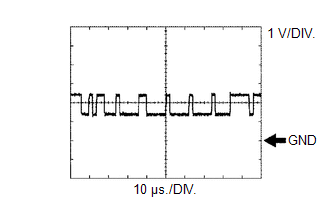 CAN Communication Signal (Reference)
 | ECM Terminal Name | Between CANL and E1, or CANN and E1 |
| Tester Range | 1 V/DIV., 10 μs./DIV. |
| Condition | Power switch on (IG) |
HINT:
The waveform varies depending on the CAN communication signal.
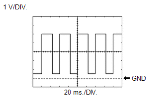
WAVEFORM 14
Cooling Fan Control Signal| ECM Terminal Name | Between RFC and E1 |
| Tester Range | 1 V/DIV., 20 ms./DIV. |
| Condition | Power switch on (IG), A/C switch on (max cool) |
HINT:
The duty ratio varies depending on the engine coolant temperature.
WAVEFORM 15
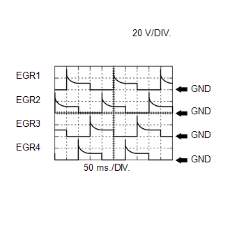 EGR Valve Assembly Signal
 | ECM Terminal Name | Between EGR1 and E1 Between EGR2 and E1 Between EGR3 and E1 Between EGR4 and E1 |
| Tester Range | 20 V/DIV., 50 ms./DIV. |
| Condition | EGR valve operating |
WAVEFORM 16
 Camshaft Position Sensor Signal
 | ECM Terminal Name | Between VV1+ and VV1- |
| Tester Range | 5 V/DIV., 20 ms./DIV. |
| Condition | Idling with warm engine |
HINT:
The wavelength becomes shorter as the engine speed increases.
READ NEXT:
 Diagnosis System
DIAGNOSIS SYSTEM DESCRIPTION When troubleshooting OBD II (On-Board Diagnostics) vehicles, the Techstream (complying with SAE J1978) must be connected to the DLC3 (Data Link Connector 3) of the vehicl
Dtc Check / Clear
DTC CHECK / CLEAR NOTICE: When the diagnosis system is changed from normal mode to check mode or vice versa, all DTCs and freeze frame data recorded in normal mode are cleared. Before changing modes,
Freeze Frame Data
FREEZE FRAME DATA DESCRIPTION The ECM records vehicle and driving condition information as freeze frame data the moment a DTC is stored. When troubleshooting, freeze frame data can be helpful in dete
SEE MORE:
Generator Position Sensor Circuit Range / Performance (P0A4C-518,P0A4C-811)
DTC SUMMARY MALFUNCTION DESCRIPTION These DTCs indicate that a large current flowed in the inverter for the generator. The cause of this malfunction may be one of the following: Area Main Malfunction Description Step Inverter low-voltage circuit The connectors are not connected properly
Components
COMPONENTS ILLUSTRATION *1 DECK FLOOR BOX LH *2 NO. 3 DECK BOARD SUB-ASSEMBLY *3 REAR DECK FLOOR BOX *4 AUXILIARY BATTERY NEGATIVE TERMINAL N*m (kgf*cm, ft.*lbf): Specified torque - - ILLUSTRATION *A for Compact Size Spare Tire *B for Full Size Spare Tire
