Lexus NX: Removal
REMOVAL
CAUTION / NOTICE / HINT
NOTICE:
- Do not replace the spiral cable with the battery connected and the power switch on (IG).
- Do not rotate the spiral cable when the following conditions are met: 1) The steering wheel is removed, 2) the battery is connected, and 3) thepower switch on (IG).
- Ensure that the steering wheel assembly is installed and aligned straight when inspecting the steering sensor.
- Do not remove the steering sensor from the spiral cable.
PROCEDURE
1. REMOVE STEERING WHEEL ASSEMBLY
Click here .gif)
2. REMOVE CRUISE CONTROL MAIN SWITCH
Click here
3. REMOVE STEERING PAD SWITCH ASSEMBLY
Click here
4. REMOVE SHIFT PADDLE SWITCH (TRANSMISSION SHIFT SWITCH ASSEMBLY)
| (a) Disengage the guide to disconnect the No. 1 switch wire from the steering wheel assembly. |
|
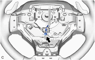
(b) Disconnect the No. 1 switch wire connector.
| (c) Remove the 4 screws, and disconnect the 2 shift paddle switches (transmission shift switch assemblies) from the steering wheel assembly. |
|
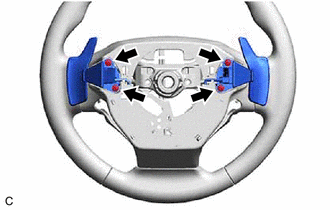
| (d) Disconnect the 2 shift paddle switch (transmission shift switch assembly) connectors to remove the 2 shift paddle switches (transmission shift switch assemblies) from the No. 1 switch wire. |
|
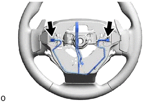
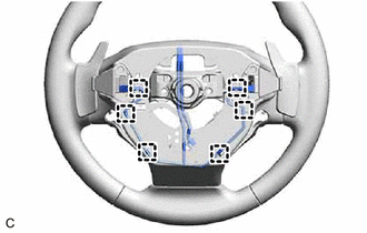
| (e) Disengage the 6 guides to remove the 2 shift paddle switches (transmission shift switch assemblies) with No. 1 switch wire from the steering wheel assembly. |
|
READ NEXT:
 Inspection
INSPECTION PROCEDURE 1. INSPECT SHIFT PADDLE SWITCH (TRANSMISSION SHIFT SWITCH ASSEMBLY) (a) Measure the resistance according to the value(s) in the table below. Standard Resistance: Shift Paddle
Installation
INSTALLATION CAUTION / NOTICE / HINT NOTICE:
Do not replace the spiral cable with the battery connected and the power switch on (IG).
Do not rotate the spiral cable when the following conditions
SEE MORE:
Steering Vibrator Component Internal Failure (C1A7496)
DESCRIPTION If the forward recognition camera receives a steering vibration ECU malfunction signal, DTC C1A7496 is stored. DTC No. Detection Item DTC Detection Condition Trouble Area C1A7496 Steering Vibrator Component Internal Failure 3 seconds after the power switch is turned on (
Components
COMPONENTS ILLUSTRATION *1 DECK FLOOR BOX LH *2 NO. 3 DECK BOARD SUB-ASSEMBLY *3 REAR DECK FLOOR BOX *4 NEGATIVE AUXILIARY BATTERY TERMINAL N*m (kgf*cm, ft.*lbf): Specified torque - - ILLUSTRATION *1 DCM (TELEMATICS TRANSCEIVER) *2 MOBILEPHONE BATTERY
