Lexus NX: Power Switch Illumination Circuit
DESCRIPTION
The illuminated entry system controls the power switch illumination.
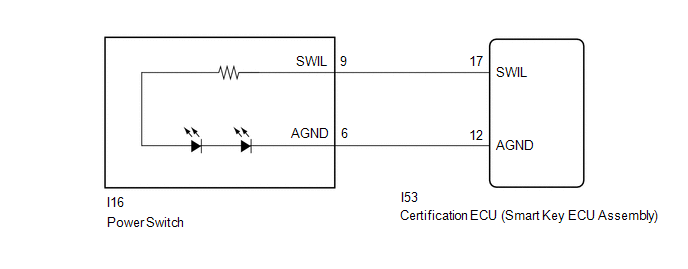
WIRING DIAGRAM
CAUTION / NOTICE / HINT
NOTICE:
- Recognition code registration is necessary when replacing the main body ECU (multiplex network body ECU).
- If the main body ECU (multiplex network body ECU) is replaced, refer to Registration.
PROCEDURE
| 1. | PERFORM ACTIVE TEST USING TECHSTREAM (POWER/ENGINE SW LIGHT) |
(a) Using the GTS, perform the Active Test.
Click here .gif)
| Tester Display | Measurement Item | Control Range | Diagnostic Note |
|---|---|---|---|
| Power/Engine SW Light | Power switch illumination | ON or OFF | - |
| Tester Display |
|---|
| Power/Engine SW Light |
OK:
Power switch illumination illuminates.
| Power switch illumination illuminates | .gif) | PROCEED TO NEXT SUSPECTED AREA SHOWN IN PROBLEM SYMPTOMS TABLE |
|
.gif)
| 2. | INSPECT POWER SWITCH |
(a) Remove the power switch.
Click here
(b) Inspect the power switch.
Click here
| NG | | REPLACE POWER SWITCH |
|
| 3. | CHECK HARNESS AND CONNECTOR (POWER SWITCH - CERTIFICATION ECU [SMART KEY ECU ASSEMBLY]) |
(a) Disconnect the I16 power switch connector.
(b) Disconnect the I53 certification ECU (smart key ECU assembly) connector.
(c) Measure the resistance according to the value(s) in the table below.
Standard Resistance:
| Tester Connection | Condition | Specified Condition |
|---|---|---|
| I16-9 (SWIL) - I53-17 (SWIL) | Always | Below 1 Ω |
| I16-6 (AGND) - I53-12 (AGND) | Always | Below 1 Ω |
| I16-9 (SWIL) or I53-17 (SWIL) - Body ground | Always | 10 kΩ or higher |
| I16-6 (AGND) or I53-12 (AGND) - Body ground | Always | 10 kΩ or higher |
| OK | | REPLACE CERTIFICATION ECU (SMART KEY ECU ASSEMBLY) |
| NG | | REPAIR OR REPLACE HARNESS OR CONNECTOR |
READ NEXT:
 Door Unlock Detection Switch Circuit
DESCRIPTION The main body ECU (multiplex network body ECU) detects the condition of each door unlock detection switch. WIRING DIAGRAM CAUTION / NOTICE / HINT NOTICE:
Recognition code registration
Luggage Compartment Room Light
ComponentsCOMPONENTS ILLUSTRATION *1 NO. 1 LUGGAGE COMPARTMENT LIGHT ASSEMBLY - - RemovalREMOVAL PROCEDURE 1. REMOVE NO. 1 LUGGAGE COMPARTMENT LIGHT ASSEMBLY (for LH Side) (a) Put prote
SEE MORE:
How To Proceed With Troubleshooting
CAUTION / NOTICE / HINT HINT: Use these procedures to troubleshoot the adaptive variable suspension system. *: Use the Techstream. PROCEDURE 1. VEHICLE BROUGHT TO WORKSHOP
NEXT 2. PROBLEM SYMPTOM CONFIRMATION
NEXT 3. INSPECT AUXILIARY BATTERY
Data List / Active Test
DATA LIST / ACTIVE TEST READ DATA LIST HINT: Using the Techstream to read the Data List allows the values or states of switches, sensors, actuators and other items to be read without removing any parts. This non-intrusive inspection can be very useful because intermittent conditions or signals may b
