Lexus NX: Kick Sensor Circuit (B2205)
DESCRIPTION
B2205 is output when the multiplex network door ECU detects that the kick door control sensor is stuck on.
| DTC No. | Detection Item | DTC Detection Condition | Trouble Area |
|---|---|---|---|
| B2205 | Kick Sensor Circuit | One of the following conditions is met for approximately 60 seconds or more:
|
|
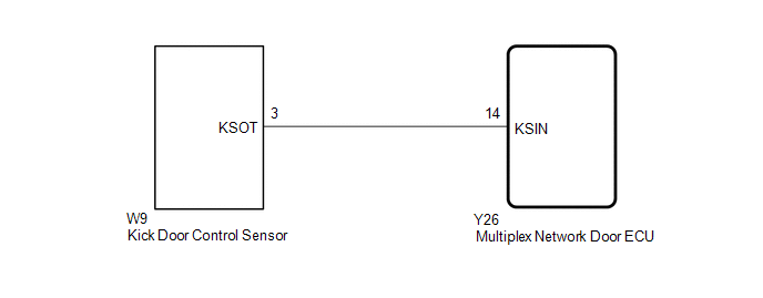
WIRING DIAGRAM
CAUTION / NOTICE / HINT
NOTICE:
- Before troubleshooting, make sure that the kick door control sensor is not damaged.
-
Before troubleshooting, be sure to read Precautions for Hands Free Power Back Door.
Click here
.gif)
-
If the multiplex network door ECU has been removed and installed or replaced, or if any of the connectors has been disconnected, initialize the power back door system.
Click here
-
After performing work, using the Techstream, read the Data List item "Kick Sensor Connection" and check that the kick door control sensor is connected.
Click here
-
Check the smart access system with push-button start (for Entry Function) first before troubleshooting the power back door system.
Click here
PROCEDURE
| 1. | CHECK FOR DTC |
(a) Clear the DTCs.
Click here
(b) Wait for approximately 60 seconds.
(c) Check for DTCs.
Click here
| Result | Proceed to |
|---|---|
| DTC is not output | A |
| DTC B2205 is output | B |
| A | .gif) | USE SIMULATION METHOD TO CHECK |
|
.gif)
| 2. | CHECK FOR DTC |
(a) Disconnect the W9 kick door control sensor connector.
(b) Wait for approximately 60 seconds.
(c) Clear the DTCs.
Click here
(d) Check for DTCs.
Click here
| Result | Proceed to |
|---|---|
| DTC is not output | A |
| DTC B2205 is output | B |
| A | | REPLACE KICK DOOR CONTROL SENSOR |
|
| 3. | CHECK HARNESS AND CONNECTOR (MULTIPLEX NETWORK DOOR ECU - KICK DOOR CONTROL SENSOR) |
(a) Disconnect the Y26 multiplex network door ECU connector.
(b) Disconnect the W9 kick door control sensor connector.
(c) Measure the resistance according to the value(s) in the table below.
Standard Resistance:
| Tester Connection | Condition | Specified Condition |
|---|---|---|
| Y26-14 (KSIN) or W9-3 (KSOT) - Body ground | Always | 10 kΩ or higher |
| OK | | REPLACE MULTIPLEX NETWORK DOOR ECU |
| NG | | REPAIR OR REPLACE HARNESS OR CONNECTOR |
READ NEXT:
 Back Door Motor Circuit (B2220)
DESCRIPTION This DTC is output when the multiplex network door ECU detects a malfunction in the motor built into the power back door unit assembly set LH or RH. DTC No. Detection Item DTC Detec
PBD Unit Pulse Sensor LH Circuit (B2226)
DESCRIPTION This DTC is output when the multiplex network door ECU detects a power back door unit assembly set LH pulse malfunction. DTC No. Detection Item DTC Detection Condition Trouble Are
PBD Unit Pulse Sensor RH Circuit (B2227)
DESCRIPTION This DTC is output when the multiplex network door ECU detects a power back door unit assembly set RH pulse malfunction. DTC No. Detection Item DTC Detection Condition Trouble Are
SEE MORE:
Drive Motor "A" Inverter Performance (P0A78-286)
DTC SUMMARY MALFUNCTION DESCRIPTION This DTC indicates a malfunction inside the inverter for the motor. The cause of this malfunction may be one of the following: Area Main Malfunction Description Step Inverter low-voltage circuit The connectors are not connected properly 3 Hybrid
Components
COMPONENTS ILLUSTRATION *1 MAP LIGHT ASSEMBLY (PERSONAL LIGHT) *2 MAP LIGHT SUB-ASSEMBLY
