Lexus NX: Lost Communication with "Door Control Module B" (U0200)
DESCRIPTION
| DTC No. | Detection Item | DTC Detection Condition | Trouble Area | DTC Output from |
|---|---|---|---|---|
| U0200 | Lost Communication with "Door Control Module B" | There is no communication from the outer mirror control ECU assembly RH. |
| Main Body |
For vehicles with a memory.
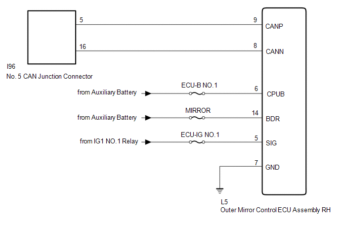
WIRING DIAGRAM
CAUTION / NOTICE / HINT
NOTICE:
- Inspect the fuses for circuits related to this system before performing the following procedure.
- Before measuring the resistance of the CAN bus, turn the power switch off and leave the vehicle for 1 minute or more without operating the key or any switches, or opening or closing the doors. After that, disconnect the cable from the negative (-) auxiliary battery terminal and leave the vehicle for 1 minute or more before measuring the resistance.
-
After turning the power switch off, waiting time may be required before disconnecting the cable from the negative (-) auxiliary battery terminal.
Click here
.gif)
-
When disconnecting and reconnecting the auxiliary battery.
Click here
HINT:
When disconnecting and reconnecting the auxiliary battery, there is an automatic learning function that completes learning when the respective system is used.
Click here
-
Some parts must be initialized and set when replacing or removing and installing parts.
Click here
-
Because the order of diagnosis is important to allow correct diagnosis, make sure to begin troubleshooting using How to Proceed with Troubleshooting when CAN communication system related DTCs are output.
Click here
-
After performing repairs, perform the DTC check procedure and confirm that the DTCs are not output again.
DTC check procedure: Turn the power switch on (IG) and wait at least 20 seconds.
-
After the repair, perform the CAN bus check and check that all the ECUs and sensors connected to the CAN communication system are displayed.
Click here
PROCEDURE
| 1. | RECONFIRM DTC OUTPUT |
(a) Check for DTCs.
Body Electrical > Main Body > Trouble CodesHINT:
If DTC U1002 is output from the gateway of the main body ECU (multiplex network body ECU), this indicates a sub bus 1 malfunction. Troubleshoot for DTC U1002 and check for malfunctions in sub bus 1.
| Result | Proceed to |
|---|---|
| DTC U1002 is not output from main body ECU (multiplex network body ECU) | A |
| DTC U1002 is output from main body ECU (multiplex network body ECU) | B |
| B | .gif) | GO TO DIAGNOSIS PROCEDURE INDICATED BY OUTPUT DTC |
|
.gif)
| 2. | CHECK FOR OPEN IN CAN BUS WIRE (OUTER MIRROR CONTROL ECU ASSEMBLY RH BRANCH WIRE) |
| (a) Disconnect the cable from the negative (-) auxiliary battery terminal. |
|
(b) Disconnect the outer mirror control ECU assembly RH connector.
(c) Measure the resistance according to the value(s) in the table below.
Standard Resistance:
| Tester Connection | Condition | Specified Condition |
|---|---|---|
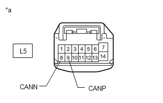
| L5-9 (CANP) - L5-8 (CANN) | Cable disconnected from negative (-) auxiliary battery terminal | 54 to 69 Ω |
| NG | | REPAIR OR REPLACE CAN BRANCH WIRE OR CONNECTOR (OUTER MIRROR CONTROL ECU ASSEMBLY RH) |
|
| 3. | CHECK HARNESS AND CONNECTOR (OUTER MIRROR CONTROL ECU ASSEMBLY RH - BATTERY AND BODY GROUND) |
| (a) Reconnect the cable to the negative (-) auxiliary battery terminal. |
|
(b) Measure the voltage according to the value(s) in the table below.
Standard Voltage:
| Tester Connection | Switch Condition | Specified Condition |
|---|---|---|
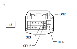
| L5-5 (SIG) - Body ground | Power switch on (IG) | 11 to 14 V |
| L5-6 (CPUB) - Body ground | Power switch off | 11 to 14 V |
| L5-14 (BDR) - Body ground | Power switch off | 11 to 14 V |
(c) Measure the resistance according to the value(s) in the table below.
Standard Resistance:
| Tester Connection | Condition | Specified Condition |
|---|---|---|
| L5-7 (GND) - Body ground | Always | Below 1 Ω |
| OK | | REPLACE OUTER MIRROR CONTROL ECU ASSEMBLY RH |
| NG | | REPAIR OR REPLACE HARNESS OR CONNECTOR |
READ NEXT:
 Lost Communication with "Seat Control Module A" (U0208)
DESCRIPTION DTC No. Detection Item DTC Detection Condition Trouble Area DTC Output from U0208 Lost Communication with "Seat Control Module A" There is no communication from the fron
Lost Communication with Rear Gate Module (U0230)
DESCRIPTION DTC No. Detection Item DTC Detection Condition Trouble Area DTC Output from U0230 Lost Communication with Rear Gate Module There is no communication from the multiplex n
Lost Communication with Gateway Module (Main Body ECU) (U1002)
DESCRIPTION
The main body ECU (multiplex network body ECU) will store this DTC when no signals can be received from the ECUs that have been memorized as those that are connected to sub bus 1.
Whe
SEE MORE:
Removal
REMOVAL PROCEDURE 1. REMOVE FRONT SUSPENSION CROSSMEMBER SUB-ASSEMBLY Click here 2. REMOVE FRONT STABILIZER LINK ASSEMBLY LH (a) Remove the nut and front stabilizer link assembly LH. HINT: If the ball joint turns together with the nut, use a 6 mm hexagon wrench to hold the stud bolt.
Battery Control System (P3000-388)
DESCRIPTION The hybrid vehicle control ECU alerts the driver and performs fail-safe control based on error signals received from the battery voltage sensor. This DTC is stored when the SOC (state of charge) of the HV battery starts to drop as a result of leaving the shift lever in N, running out of
