- +B short
- Ground short
Lexus NX: Lost Communication with Gateway Module (Main Body ECU) (U1002)
Lexus NX Service Manual / Power Source & Network / Networking / Can Communication System / Lost Communication with Gateway Module (Main Body ECU) (U1002)
DESCRIPTION
- The main body ECU (multiplex network body ECU) will store this DTC when no signals can be received from the ECUs that have been memorized as those that are connected to sub bus 1.
- When the main body ECU (multiplex network body ECU) receives a response signal from the ECUs connected to sub bus 1, the main body ECU (multiplex network body ECU) recognizes and memorizes that the ECU is connected to sub bus 1. Based on this memorized data, the main body ECU (multiplex network body ECU) monitors for malfunctions in the ECUs connected to sub bus 1 when communicating with those ECUs. If the main body ECU (multiplex network body ECU) cannot receive response signals from the ECUs that have been memorized as those connected to sub bus 1, the main body ECU (multiplex network body ECU) determines that a malfunction exists.
| DTC No. | Detection Item | DTC Detection Condition | Trouble Area | DTC Output from |
|---|---|---|---|---|
| U1002 | Lost Communication with Gateway Module (Main Body ECU) | The main body ECU (multiplex network body ECU) cannot receive signals from all ECUs that have been memorized as those connected to sub bus 1. |
| Main Body |
HINT:
This diagnostic procedure is for when DTC U1002 is output by the main body ECU (multiplex network body ECU) (Techstream display: Main Body).
WIRING DIAGRAM
CAUTION / NOTICE / HINT
CAUTION:
When performing the confirmation driving pattern, obey all speed limits and traffic laws.
NOTICE:
- Inspect the fuses for circuits related to this system before performing the following procedure.
- Before measuring the resistance of the CAN bus, turn the power switch off and leave the vehicle for 1 minute or more without operating the key or any switches, or opening or closing the doors. After that, disconnect the cable from the negative (-) auxiliary battery terminal and leave the vehicle for 1 minute or more before measuring the resistance.
-
After turning the power switch off, waiting time may be required before disconnecting the cable from the negative (-) auxiliary battery terminal.
Click here
.gif)
-
When disconnecting and reconnecting the auxiliary battery.
Click here
HINT:
When disconnecting and reconnecting the auxiliary battery, there is an automatic learning function that completes learning when the respective system is used.
Click here
-
Some parts must be initialized and set when replacing or removing and installing parts.
Click here
-
Because the order of diagnosis is important to allow correct diagnosis, make sure to begin troubleshooting using How to Proceed with Troubleshooting when CAN communication system related DTCs are output.
Click here
-
After performing repairs, perform the DTC check procedure and confirm that the DTCs are not output again.
DTC check procedure: Turn the power switch on (IG) and wait for 1 minute or more. Then operate the suspected malfunctioning system and drive the vehicle at 60 km/h (37 mph) or more for 5 minutes or more.
-
After the repair, perform the CAN bus check and check that all the ECUs and sensors connected to the CAN communication system are displayed as normal.
Click here
HINT:
- Operating the power switch, any switches or any doors triggers related ECU and sensor communication with the CAN, which causes resistance variation.
- Even after DTCs are cleared, if a DTC is stored again after driving the vehicle for a while, the malfunction may be occurring due to vibration of the vehicle. In such a case, wiggling the ECUs or wire harness while performing the inspection below may help determine the cause of the malfunction.
PROCEDURE
| 1. | CHECK SUB BUS 1 |
(a) Disconnect the cable from the negative (-) auxiliary battery terminal.
| (b) Measure the resistance according to the value(s) in the table below. Standard Resistance:
|
|
| Result | Proceed to |
|---|---|
| OK | A |
| Open circuit in CAN main bus lines | B |
| Between Lines | C |
| | D |
| B | .gif) | GO TO STEP 3 |
| C | | GO TO STEP 12 |
| D | | GO TO STEP 21 |
|
.gif)
| 2. | CHECK FOR DTC OUTPUT |
(a) Reconnect the cable to the negative (-) auxiliary battery terminal.
(b) Connect the Techstream to the DLC3.
(c) Turn the power switch on (IG).
(d) Turn the Techstream on.
(e) Clear the DTCs.
Body Electrical > Main Body > Clear DTCs(f) Turn the power switch off.
(g) Turn the power switch on (IG).
(h) Check for DTCs.
Body Electrical > Main Body > Trouble Codes| Result | Proceed to |
|---|---|
| DTC U1002 is not output from main body ECU (multiplex network body ECU) (Techstream display: Main Body) | A |
| DTC U1002 is output from main body ECU (multiplex network body ECU) (Techstream display: Main Body) | B |
| A | | USE SIMULATION METHOD TO CHECK |
| B | | REPLACE MAIN BODY ECU (MULTIPLEX NETWORK BODY ECU) |
| 3. | CHECK FOR OPEN IN CAN BUS WIRE (NO. 6 CAN JUNCTION CONNECTOR) |
| (a) Disconnect the No. 6 CAN junction connector. |
|
(b) Measure the resistance according to the value(s) in the table below.
Standard Resistance:
| Tester Connection | Condition | Specified Condition | Connected to |
|---|---|---|---|
| I97-5 (CANH) - I97-16 (CANL) | Cable disconnected from negative (-) auxiliary battery terminal | 108 to 132 Ω | No. 8 CAN junction connector |
| I97-6 (CANH) - I97-17 (CANL) | Cable disconnected from negative (-) auxiliary battery terminal | 108 to 132 Ω | No. 5 CAN junction connector |
| Result | Proceed to |
|---|---|
| OK | A |
| NG (No. 8 CAN junction connector CAN main wire) | B |
| NG (No. 5 CAN junction connector CAN main wire) | C |
| A | | REPLACE NO. 5 CAN JUNCTION CONNECTOR |
| C | | GO TO STEP 8 |
|
| 4. | CONNECT CONNECTOR |
(a) Connect the I97 No. 6 CAN junction connector.
|
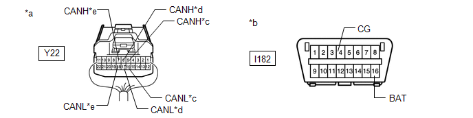
| 5. | CHECK FOR OPEN IN CAN BUS WIRE (NO. 8 CAN JUNCTION CONNECTOR) |
| (a) Disconnect the No. 8 CAN junction connector. |
|
(b) Measure the resistance according to the value(s) in the table below.
Standard Resistance:
| Tester Connection | Condition | Specified Condition | Connected to |
|---|---|---|---|
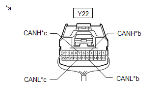
| Y22-5 (CANH) - Y22-16 (CANL) | Cable disconnected from negative (-) auxiliary battery terminal | 108 to 132 Ω | No. 6 CAN junction connector |
| Y22-7 (CANH) - Y22-18 (CANL) | Cable disconnected from negative (-) auxiliary battery terminal | 108 to 132 Ω | No. 2 CAN junction terminal |
| Result | Proceed to |
|---|---|
| OK | A |
| NG (No. 2 CAN junction terminal CAN main wire) | B |
| NG (No. 6 CAN junction connector CAN main wire) | C |
| A | | REPLACE NO. 8 CAN JUNCTION CONNECTOR |
| C | | REPAIR OR REPLACE CAN MAIN WIRE OR CONNECTOR (NO. 8 CAN JUNCTION CONNECTOR - NO. 6 CAN JUNCTION CONNECTOR) |
|
| 6. | CONNECT CONNECTOR |
(a) Connect the Y22 No. 8 CAN junction connector.
|
| 7. | CHECK FOR OPEN IN CAN BUS WIRE (NO. 2 CAN JUNCTION TERMINAL - NO. 8 CAN JUNCTION CONNECTOR) |
| (a) Disconnect the No. 2 CAN junction terminal connector. |
|
(b) Measure the resistance according to the value(s) in the table below.
Standard Resistance:
| Tester Connection | Condition | Specified Condition |
|---|---|---|
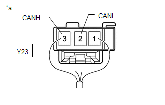
| Y23-3 (CANH) - Y23-2 (CANL) | Cable disconnected from negative (-) auxiliary battery terminal | 108 to 132 Ω |
| OK | | REPLACE NO. 2 CAN JUNCTION TERMINAL |
| NG | | REPAIR OR REPLACE CAN MAIN WIRE OR CONNECTOR (NO. 2 CAN JUNCTION TERMINAL - NO. 8 CAN JUNCTION CONNECTOR) |
| 8. | CONNECT CONNECTOR |
(a) Connect the I97 No. 6 CAN junction connector.
|
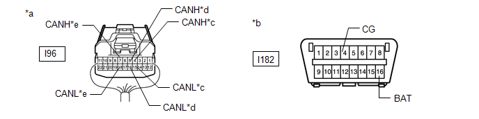
| 9. | CHECK FOR OPEN IN CAN BUS WIRE (NO. 5 CAN JUNCTION CONNECTOR) |
| (a) Disconnect the No. 5 CAN junction connector. |
|
(b) Measure the resistance according to the value(s) in the table below.
Standard Resistance:
| Tester Connection | Condition | Specified Condition | Connected to |
|---|---|---|---|
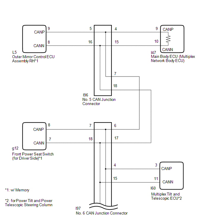
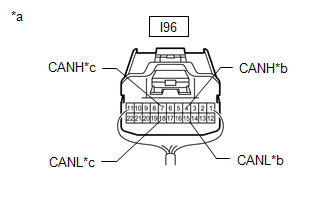
| I96-4 (CANH) - I96-15 (CANL) | Cable disconnected from negative (-) auxiliary battery terminal | 108 to 132 Ω | Main body ECU (multiplex network body ECU) |
| I96-7 (CANH) - I96-18 (CANL) | Cable disconnected from negative (-) auxiliary battery terminal | 108 to 132 Ω | No. 6 CAN junction connector |
| Result | Proceed to |
|---|---|
| OK | A |
| NG (Main body ECU [multiplex network ECU] CAN main wire) | B |
| NG (No. 6 CAN junction connector CAN main wire) | C |
| A | | REPLACE NO. 5 CAN JUNCTION CONNECTOR |
| C | | REPAIR OR REPLACE CAN MAIN WIRE OR CONNECTOR (NO. 5 CAN JUNCTION CONNECTOR - NO. 6 CAN JUNCTION CONNECTOR) |
|
| 10. | CONNECT CONNECTOR |
(a) Connect the I96 No. 5 CAN junction connector.
|
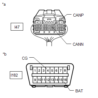
| 11. | CHECK FOR OPEN IN CAN BUS WIRE (MAIN BODY ECU [MULTIPLEX NETWORK BODY ECU] - NO. 4 CAN JUNCTION CONNECTOR) |
| (a) Disconnect the main body ECU (multiplex network body ECU) connector. |
|
(b) Measure the resistance according to the value(s) in the table below.
Standard Resistance:
| Tester Connection | Condition | Specified Condition |
|---|---|---|
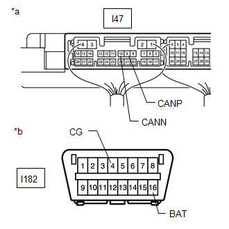
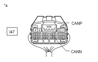
| I47-9 (CANP) - I47-10 (CANN) | Cable disconnected from negative (-) auxiliary battery terminal | 108 to 132 Ω |
| OK | | REPLACE MAIN BODY ECU (MULTIPLEX NETWORK BODY ECU) |
| NG | | REPAIR OR REPLACE CAN MAIN WIRE OR CONNECTOR (MAIN BODY ECU [MULTIPLEX NETWORK BODY ECU] - NO. 5 CAN JUNCTION CONNECTOR) |
| 12. | CHECK FOR SHORT IN CAN BUS WIRES (NO. 6 CAN JUNCTION CONNECTOR) |
| (a) Disconnect the No. 6 CAN junction connector. |
|
(b) Measure the resistance according to the value(s) in the table below.
Standard Resistance:
| Tester Connection | Condition | Specified Condition | Connected to |
|---|---|---|---|
|
*1: for Power Tilt and Power Telescopic Steering Column
*2: w/ Memory | |||
| I97-4 (CANH) - I97-15 (CANL) | Cable disconnected from negative (-) auxiliary battery terminal | 200 Ω or higher | Multiplex tilt and telescopic ECU*1 |
| I97-5 (CANH) - I97-16 (CANL) | Cable disconnected from negative (-) auxiliary battery terminal | 108 to 132 Ω | No. 8 CAN junction connector |
| I97-6 (CANH) - I97-17 (CANL) | Cable disconnected from negative (-) auxiliary battery terminal | 108 to 132 Ω | No. 5 CAN junction connector |
| I97-7 (CANH) - I97-18 (CANL) | Cable disconnected from negative (-) auxiliary battery terminal | 200 Ω or higher | Front power seat switch (for driver side)*2 |
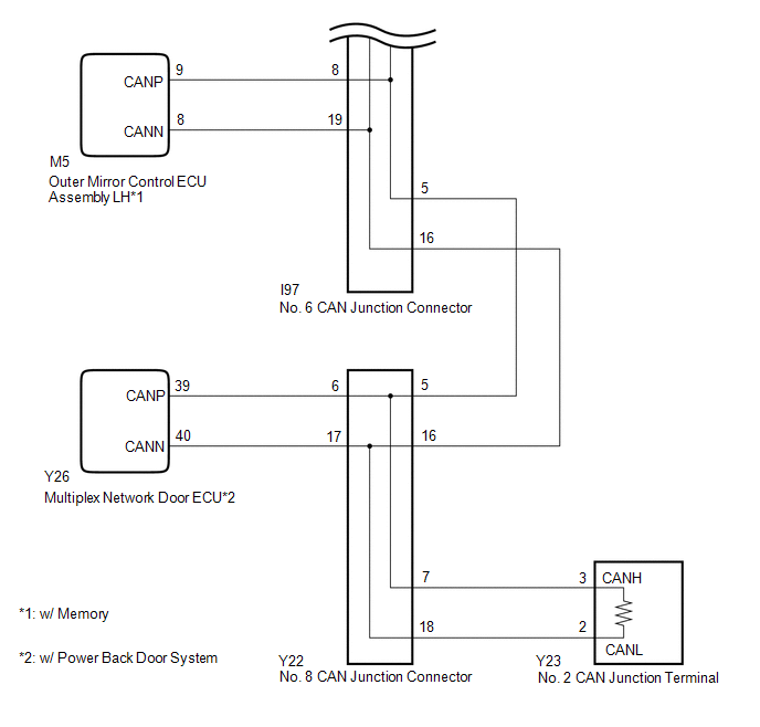
| I97-8 (CANH) - I97-19 (CANL) | Cable disconnected from negative (-) auxiliary battery terminal | 200 Ω or higher | Outer mirror control ECU assembly LH*2 |
| Result | Proceed to |
|---|---|
| OK | A |
| NG (No. 8 CAN junction connector CAN main wire) | B |
| NG (No. 5 CAN junction connector CAN main wire) | C |
| NG (Wire to ECU or sensor) | D |
| A | | REPLACE NO. 6 CAN JUNCTION CONNECTOR |
| C | | GO TO STEP 17 |
| D | | GO TO STEP 28 |
|
| 13. | CONNECT CONNECTOR |
(a) Connect the I97 No. 6 CAN junction connector.
|
| 14. | CHECK FOR SHORT IN CAN BUS WIRES (NO. 8 CAN JUNCTION CONNECTOR) |
| (a) Disconnect the No. 8 CAN junction connector. |
|
(b) Measure the resistance according to the value(s) in the table below.
Standard Resistance:
| Tester Connection | Condition | Specified Condition | Connected to |
|---|---|---|---|
| *: w/ Power Back Door System | |||
| Y22-5 (CANH) - Y22-16 (CANL) | Cable disconnected from negative (-) auxiliary battery terminal | 108 to 132 Ω | No. 6 CAN junction connector |
| Y22-6 (CANH) - Y22-17 (CANL) | Cable disconnected from negative (-) auxiliary battery terminal | 200 Ω or higher | Multiplex network door ECU* |
| Y22-7 (CANH) - Y22-18 (CANL) | Cable disconnected from negative (-) auxiliary battery terminal | 108 to 132 Ω | No. 2 CAN junction terminal |
| Result | Proceed to |
|---|---|
| OK | A |
| NG (No. 2 CAN junction terminal CAN main wire) | B |
| NG (No. 6 CAN junction connector CAN main wire) | C |
| NG (Wire to ECU or sensor) | D |
| A | | REPLACE NO. 8 CAN JUNCTION CONNECTOR |
| C | | REPAIR OR REPLACE CAN MAIN WIRE OR CONNECTOR (NO. 8 CAN JUNCTION CONNECTOR - NO. 6 CAN JUNCTION CONNECTOR) |
| D | | GO TO STEP 28 |
|
| 15. | CONNECT CONNECTOR |
(a) Connect the Y22 No. 8 CAN junction connector.
|
| 16. | CHECK FOR SHORT IN CAN BUS WIRES (NO. 2 CAN JUNCTION TERMINAL - NO. 8 CAN JUNCTION CONNECTOR) |
| (a) Disconnect the No. 2 CAN junction terminal connector. |
|
(b) Measure the resistance according to the value(s) in the table below.
Standard Resistance:
| Tester Connection | Condition | Specified Condition |
|---|---|---|
| Y23-3 (CANH) - Y23-2 (CANL) | Cable disconnected from negative (-) auxiliary battery terminal | 108 to 132 Ω |
| OK | | REPLACE NO. 2 CAN JUNCTION TERMINAL |
| NG | | REPAIR OR REPLACE CAN MAIN WIRE OR CONNECTOR (NO. 2 CAN JUNCTION TERMINAL - NO. 8 CAN JUNCTION CONNECTOR) |
| 17. | CONNECT CONNECTOR |
(a) Connect the I97 No. 6 CAN junction connector.
|
| 18. | CHECK FOR SHORT IN CAN BUS WIRES (NO. 5 CAN JUNCTION CONNECTOR) |
| (a) Disconnect the No. 5 CAN junction connector. |
|
(b) Measure the resistance according to the value(s) in the table below.
Standard Resistance:
| Tester Connection | Condition | Specified Condition | Connected to |
|---|---|---|---|
| *: w/ Memory | |||
| I96-4 (CANH) - I96-15 (CANL) | Cable disconnected from negative (-) auxiliary battery terminal | 108 to 132 Ω | Main body ECU (multiplex network body ECU) |
| I96-5 (CANH) - I96-16 (CANL) | Cable disconnected from negative (-) auxiliary battery terminal | 200 Ω or higher | Outer mirror control ECU assembly RH* |
| I96-7 (CANH) - I96-18 (CANL) | Cable disconnected from negative (-) auxiliary battery terminal | 108 to 132 Ω | No. 6 CAN junction connector |
| Result | Proceed to |
|---|---|
| OK | A |
| NG (Main body ECU [multiplex network ECU] CAN main wire) | B |
| NG (No. 6 CAN junction connector CAN main wire) | C |
| NG (Wire to ECU or sensor) | D |
| A | | REPLACE NO. 5 CAN JUNCTION CONNECTOR |
| C | | REPAIR OR REPLACE CAN MAIN WIRE OR CONNECTOR (NO. 5 CAN JUNCTION CONNECTOR - NO. 6 CAN JUNCTION CONNECTOR) |
| D | | GO TO STEP 28 |
|
| 19. | CONNECT CONNECTOR |
(a) Connect the I96 No. 5 CAN junction connector.
|
| 20. | CHECK FOR SHORT IN CAN BUS WIRES (MAIN BODY ECU [MULTIPLEX NETWORK BODY ECU] - NO. 5 CAN JUNCTION CONNECTOR) |
| (a) Disconnect the main body ECU (multiplex network body ECU) connector. |
|
(b) Measure the resistance according to the value(s) in the table below.
Standard Resistance:
| Tester Connection | Condition | Specified Condition |
|---|---|---|
| I47-9 (CANP) - I47-10 (CANN) | Cable disconnected from negative (-) auxiliary battery terminal | 108 to 132 Ω |
| OK | | REPLACE MAIN BODY ECU (MULTIPLEX NETWORK BODY ECU) |
| NG | | REPAIR OR REPLACE CAN MAIN WIRE OR CONNECTOR (MAIN BODY ECU [MULTIPLEX NETWORK BODY ECU] - NO. 5 CAN JUNCTION CONNECTOR) |
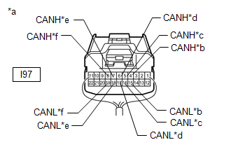
| 21. | CHECK FOR SHORT IN CAN BUS WIRES (NO. 6 CAN JUNCTION CONNECTOR) |
(a) Disconnect the No. 6 CAN junction connector.
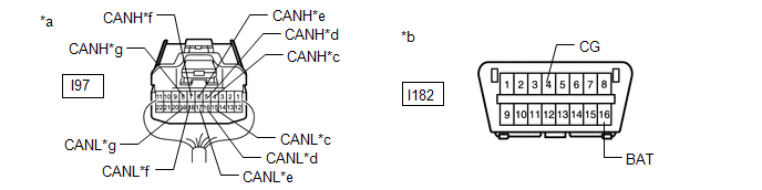
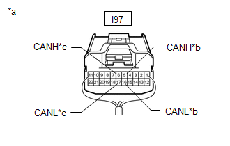
| *a | Rear view of wire harness connector (to No. 6 CAN Junction Connector) | *b | Front view of DLC3 |
| *c | to Multiplex Tilt and Telescopic ECU (for Power Tilt and Power Telescopic Steering Column) | *d | to No. 8 CAN Junction Connector |
| *e | to No. 5 CAN Junction Connector | *f | to Front Power Seat Switch (for Driver Side) (w/ Memory) |
| *g | to Outer Mirror Control ECU Assembly LH (w/ Memory) | - | - |
(b) Measure the resistance according to the value(s) in the table below.
Standard Resistance:
| Tester Connection | Condition | Specified Condition | Connected to |
|---|---|---|---|
|
*1: for Power Tilt and Power Telescopic Steering Column
*2: w/ Memory | |||
| I97-4 (CANH) - I182-16 (BAT) | Cable disconnected from negative (-) auxiliary battery terminal | 6 kΩ or higher | Multiplex Tilt and Telescopic ECU*1 |
| I97-15 (CANL) - I182-16 (BAT) | |||
| I97-4 (CANH) - I182-4 (CG) | Cable disconnected from negative (-) auxiliary battery terminal | 200 Ω or higher | |
| I97-15 (CANL) - I182-4 (CG) | |||
| I97-5 (CANH) - I182-16 (BAT) | Cable disconnected from negative (-) auxiliary battery terminal | 6 kΩ or higher | No. 8 CAN junction connector |
| I97-16 (CANL) - I182-16 (BAT) | |||
| I97-5 (CANH) - I182-4 (CG) | Cable disconnected from negative (-) auxiliary battery terminal | 200 Ω or higher | |
| I97-16 (CANL) - I182-4 (CG) | |||
| I97-6 (CANH) - I182-16 (BAT) | Cable disconnected from negative (-) auxiliary battery terminal | 6 kΩ or higher | No. 5 CAN junction connector |
| I97-17 (CANL) - I182-16 (BAT) | |||
| I97-6 (CANH) - I182-4 (CG) | Cable disconnected from negative (-) auxiliary battery terminal | 200 Ω or higher | |
| I97-17 (CANL) - I182-4 (CG) | |||
| I97-7 (CANH) - I182-16 (BAT) | Cable disconnected from negative (-) auxiliary battery terminal | 6 kΩ or higher | Front power seat switch (for driver side)*2 |
| I97-18 (CANL) - I182-16 (BAT) | |||
| I97-7 (CANH) - I182-4 (CG) | Cable disconnected from negative (-) auxiliary battery terminal | 200 Ω or higher | |
| I97-18 (CANL) - I182-4 (CG) | |||
| I97-8 (CANH) - I182-16 (BAT) | Cable disconnected from negative (-) auxiliary battery terminal | 6 kΩ or higher | Outer mirror control ECU assembly LH*2 |
| I97-19 (CANL) - I182-16 (BAT) | |||
| I97-8 (CANH) - I182-4 (CG) | Cable disconnected from negative (-) auxiliary battery terminal | 200 Ω or higher | |
| I97-19 (CANL) - I182-4 (CG) | |||
| Result | Proceed to |
|---|---|
| OK | A |
| NG (No. 8 CAN junction connector CAN main wire) | B |
| NG (No. 5 CAN junction connector CAN main wire) | C |
| NG (Wire to ECU or sensor) | D |
| A | | REPLACE NO. 6 CAN JUNCTION CONNECTOR |
| C | | GO TO STEP 24 |
| D | | GO TO STEP 28 |
|
| 22. | CONNECT CONNECTOR |
(a) Connect the I97 No. 5 CAN junction connector.
|
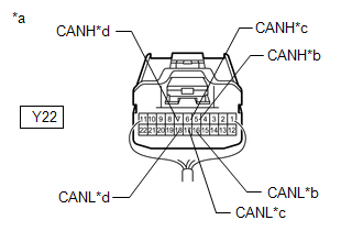
| 23. | CHECK FOR SHORT IN CAN BUS WIRES (NO. 8 CAN JUNCTION CONNECTOR) |
(a) Disconnect the No. 8 CAN junction connector.
| *a | Rear view of wire harness connector (to No. 8 CAN Junction Connector) | *b | Front view of DLC3 |
| *c | to No. 6 CAN Junction Connector | *d | to Multiplex Network Door ECU (w/ Power Back Door System) |
| *e | to No. 2 CAN Junction Terminal | - | - |
(b) Measure the resistance according to the value(s) in the table below.
Standard Resistance:
| Tester Connection | Condition | Specified Condition | Connected to |
|---|---|---|---|
| *: w/ Power Back Door System | |||
| Y22-5 (CANH) - I182-16 (BAT) | Cable disconnected from negative (-) auxiliary battery terminal | 6 kΩ or higher | No. 6 CAN junction connector |
| Y22-16 (CANL) - I182-16 (BAT) | |||
| Y22-5 (CANH) - I182-4 (CG) | Cable disconnected from negative (-) auxiliary battery terminal | 200 Ω or higher | |
| Y22-16 (CANL) - I182-4 (CG) | |||
| Y22-6 (CANH) - I182-16 (BAT) | Cable disconnected from negative (-) auxiliary battery terminal | 6 kΩ or higher | Multiplex network door ECU* |
| Y22-17 (CANL) - I182-16 (BAT) | |||
| Y22-6 (CANH) - I182-4 (CG) | Cable disconnected from negative (-) auxiliary battery terminal | 200 Ω or higher | |
| Y22-17 (CANL) - I182-4 (CG) | |||
| Y22-7 (CANH) - I182-16 (BAT) | Cable disconnected from negative (-) auxiliary battery terminal | 6 kΩ or higher | No. 2 CAN junction terminal |
| Y22-18(CANL) - I182-16 (BAT) | |||
| Y22-7 (CANH) - I182-4 (CG) | Cable disconnected from negative (-) auxiliary battery terminal | 200 Ω or higher | |
| Y22-18 (CANL) - I182-4 (CG) | |||
| Result | Proceed to |
|---|---|
| OK | A |
| NG (No. 6 CAN junction connector CAN main wire) | B |
| NG (Wire to ECU or sensor) | C |
| A | | REPLACE NO. 6 CAN JUNCTION CONNECTOR |
| B | | REPAIR OR REPLACE CAN MAIN WIRE OR CONNECTOR (NO. 8 CAN JUNCTION CONNECTOR - NO. 6 CAN JUNCTION CONNECTOR) |
| C | | GO TO STEP 28 |
| 24. | CONNECT CONNECTOR |
(a) Connect the I97 No. 6 CAN junction connector.
|
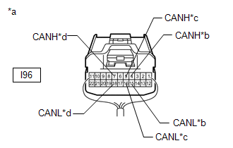
| 25. | CHECK FOR SHORT IN CAN BUS WIRES (NO. 5 CAN JUNCTION CONNECTOR) |
(a) Disconnect the No. 5 CAN junction connector.
| *a | Rear view of wire harness connector (to No. 5 CAN Junction Connector) | *b | Front view of DLC3 |
| *c | to Main Body ECU (Multiplex Network Body ECU) | *d | to Outer Mirror Control ECU Assembly RH (w/ Memory) |
| *e | to No. 6 CAN Junction Connector | - | - |
(b) Measure the resistance according to the value(s) in the table below.
Standard Resistance:
| Tester Connection | Condition | Specified Condition | Connected to |
|---|---|---|---|
| *: w/ Memory | |||
| I96-4 (CANH) - I182-16 (BAT) | Cable disconnected from negative (-) auxiliary battery terminal | 6 kΩ or higher | Main body ECU (multiplex network body ECU) |
| I96-15 (CANL) - I182-16 (BAT) | |||
| I96-4 (CANH) - I182-4 (CG) | Cable disconnected from negative (-) auxiliary battery terminal | 200 Ω or higher | |
| I96-15 (CANL) - I182-4 (CG) | |||
| I96-5 (CANH) - I182-16 (BAT) | Cable disconnected from negative (-) auxiliary battery terminal | 6 kΩ or higher | Outer mirror control ECU assembly RH* |
| I96-16 (CANL) - I182-16 (BAT) | |||
| I96-5 (CANH) - I182-4 (CG) | Cable disconnected from negative (-) auxiliary battery terminal | 200 Ω or higher | |
| I96-16 (CANL) - I182-4 (CG) | |||
| I96-7 (CANH) - I182-16 (BAT) | Cable disconnected from negative (-) auxiliary battery terminal | 6 kΩ or higher | No. 6 CAN junction connector |
| I96-18 (CANL) - I182-16 (BAT) | |||
| I96-7 (CANH) - I182-4 (CG) | Cable disconnected from negative (-) auxiliary battery terminal | 200 Ω or higher | |
| I96-18 (CANL) - I182-4 (CG) | |||
| Result | Proceed to |
|---|---|
| OK | A |
| NG (No. 6 CAN junction connector CAN main wire) | B |
| NG (Main body ECU [multiplex network body ECU] CAN main wire) | C |
| NG (Wire to ECU or sensor) | D |
| A | | REPLACE NO. 5 CAN JUNCTION CONNECTOR |
| B | | REPAIR OR REPLACE CAN MAIN WIRE OR CONNECTOR (NO. 6 CAN JUNCTION CONNECTOR - NO. 5 CAN JUNCTION CONNECTOR) |
| D | | GO TO STEP 28 |
|
| 26. | CONNECT CONNECTOR |
(a) Connect the I96 No. 5 CAN junction connector.
|
| 27. | CHECK FOR SHORT IN CAN BUS WIRES (MAIN BODY ECU) |
| (a) Disconnect the main body ECU (multiplex network body ECU) connector. |
|
(b) Measure the resistance according to the value(s) in the table below.
Standard Resistance:
| Tester Connection | Condition | Specified Condition |
|---|---|---|
| I47-9 (CANP) - I182-4 (CG) | Cable disconnected from negative (-) auxiliary battery terminal | 200 Ω or higher |
| I47-10 (CANN) - I182-4 (CG) | ||
| I47-9 (CANP) - I182-16 (BAT) | Cable disconnected from negative (-) auxiliary battery terminal | 6 kΩ or higher |
| I47-10 (CANN) - I182-16 (BAT) |
| OK | | REPLACE MAIN BODY ECU (MULTIPLEX NETWORK BODY ECU) |
| NG | | REPAIR OR REPLACE CAN MAIN WIRE CONNECTED TO MAIN BODY ECU (MAIN BODY ECU [MULTIPLEX NETWORK BODY ECU] - NO. 4 CAN JUNCTION CONNECTOR) |
| 28. | CHECK SHORT IN CAN BUS WIRES |
(a) Reconnect all wire harness connectors.
| (b) Disconnect the connector that includes terminals CANH and CANL from the ECU or sensor to which the short circuited branch line, +B or GND is connected. Standard Resistance:
HINT:
|
|

| OK | | REPLACE CORRESPONDING ECU OR SENSOR |
| NG | | REPAIR OR REPLACE CORRESPONDING ECU OR SENSOR BUS LINES OR CONNECTOR |
READ NEXT:
 Lost Communication with Tilt & (U1115)
DESCRIPTION DTC No. Detection Item DTC Detection Condition Trouble Area DTC Output from U1115 Lost Communication with Tilt & Telescopic Module There is no communication from the
Hybrid Vehicle Control ECU Communication Stop Mode
DESCRIPTION Detection Item Symptom Trouble Area Hybrid Vehicle Control ECU Communication Stop Mode Any of the following conditions are met:
Communication stop for "Hybrid Vehicle Contr
Skid Control ECU Communication Stop Mode
DESCRIPTION Detection Item Symptom Trouble Area Skid Control ECU Communication Stop Mode Any of the following conditions are met:
Communication stop for "Skid Control (ABS/VSC/TRAC)" i
SEE MORE:
Lost Communication with Body Control Module Missing Message (U014087,U015587,U016387)
DESCRIPTION These DTCs are stored when a malfunction occurs in the CAN communication circuit. DTC No. Detection Item DTC Detection Condition Trouble Area U014087 Lost Communication with Body Control Module Missing Message CAN reception error CAN communication system U015587
Removal
REMOVAL CAUTION / NOTICE / HINT HINT:
Use the same procedure for the RH and LH sides.
The procedure described below is for the LH side.
PROCEDURE 1. REMOVE FRONT BUMPER ASSEMBLY (a) except Sport Package: Click here (b) for Sport Package: Click here 2. REMOVE HEADLIGHT ASSEMBLY LH (a) App
© 2016-2026 Copyright www.lexunx.com
