Lexus NX: Removal
REMOVAL
CAUTION / NOTICE / HINT
HINT:
- Use the same procedure for the RH and LH sides.
- The procedure listed below is for the LH side.
PROCEDURE
1. REMOVE QUARTER OUTSIDE MOULDING SUB-ASSEMBLY LH
HINT:
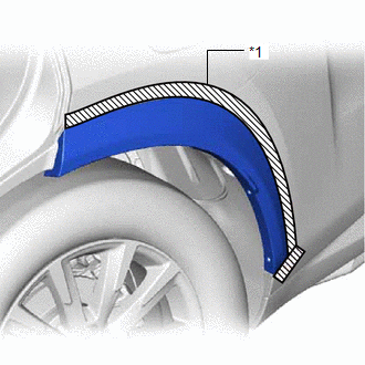
When removing the quarter outside moulding sub-assembly LH, if the No. 5 moulding tape(double-sided tape) is difficult to remove, heat the adhesive of the quarter outside moulding sub-assembly LH using a heat light.
Standard:
| Item | Temperature |
|---|---|
| Quarter Outside Moulding Sub-assembly LH | 40 to 60°C (104 to 140°F) |
NOTICE:
Do not heat the quarter outside moulding sub-assembly LH excessively.
| (a) Remove the 3 clip. |
|
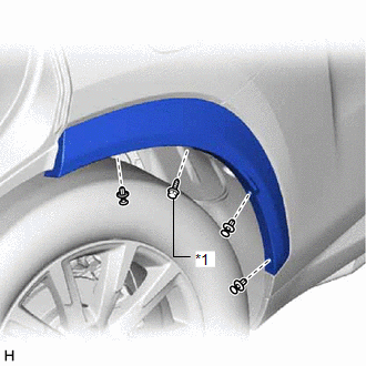
(b) Using a 4 mm hexagon socket wrench, remove the hexagon screw.
| (c) Put protective tape around the quarter outside moulding sub-assembly LH. |
|
(d) Detach the 3 clips and 4 claws and remove the quarter outside moulding sub-assembly LH.
| *1 | No. 5 Moulding Tape (Double-sided Tape) | - | - |
.png) | Direction to Pull | - | - |
READ NEXT:
 Disassembly
DISASSEMBLY CAUTION / NOTICE / HINT HINT:
Use the same procedure for the RH and LH sides.
The procedure listed below is for the LH side.
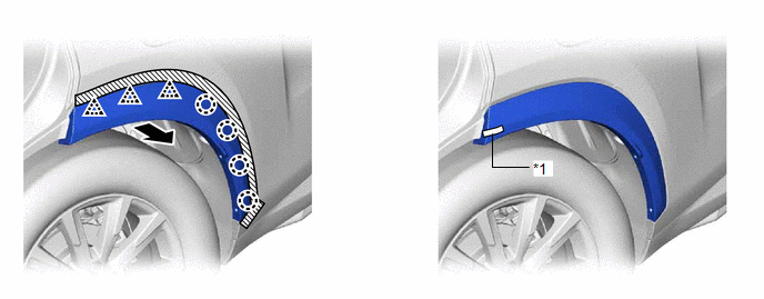
PROCEDURE 1. REMOVE NO. 5 MOULDING TAPE (a) Remove the
Reassembly
REASSEMBLY CAUTION / NOTICE / HINT HINT:
Use the same procedure for the RH and LH sides.
The procedure listed below is for the LH side.
PROCEDURE 1. INSTALL NO. 5 MOULDING TAPE (a) Clean the N
Installation
INSTALLATION CAUTION / NOTICE / HINT PROCEDURE 1. INSTALL QUARTER OUTSIDE MOULDING SUB-ASSEMBLY LH HINT: When installing the quarter outside moulding sub-assembly LH, heat the vehicle body and quarter
SEE MORE:
Removal
REMOVAL PROCEDURE 1. REMOVE FRONT BUMPER ASSEMBLY Click here 2. REMOVE NO. 3 ENGINE ROOM WIRE Click here 3. REMOVE CLEARANCE LIGHT ASSEMBLY LH (a) for LED Type Side Turn Signal Light: Click here (b) for Bulb Type Side Turn Signal Light: Click here 4. REMOVE CLEARANCE LIGHT ASSEMBLY RH HINT:
Back door
The back door can be opened using
the back door open switch, smart
access system with push-button
start or wireless remote control.
WARNING
■Caution while driving
Keep the back door closed while driving.
If the back door is left open, it may hit
nearby objects while driving or lugga
