Lexus NX: Lost Communication with Front Panel LIN (B14B2)
DESCRIPTION
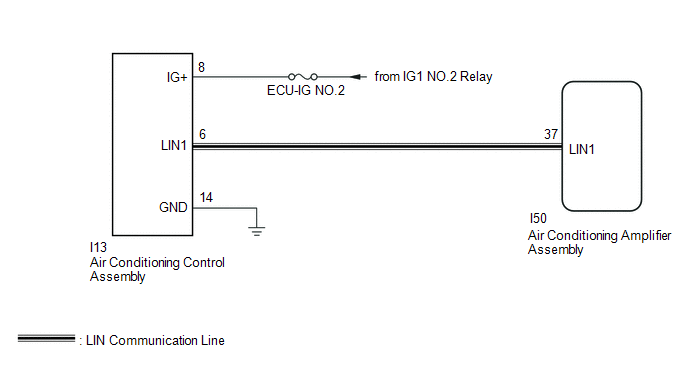
The air conditioning control assembly communicates with the air conditioning amplifier assembly through the LIN communication system.
If the LIN communication system malfunctions, the air conditioning amplifier assembly does not operate even if the air conditioning control assembly is operated.
| DTC No. | Detection Item | DTC Detection Condition | Trouble Area | Memory | Note |
|---|---|---|---|---|---|
| B14B2 | Lost Communication with Front Panel LIN | Lost communication with the air conditioning control assembly. |
| Memorized (10 seconds or more) | - |
HINT:
The air conditioning amplifier assembly stores the DTC of the respective malfunction if it has occurred for the period of time indicated in the brackets.
WIRING DIAGRAM
CAUTION / NOTICE / HINT
NOTICE:
- Inspect the fuses for circuits related to this system before performing the following procedure.
-
When the auxiliary battery is disconnected or the air conditioning amplifier assembly is replaced, be sure to perform servo motor initialization.
Click here
.gif)
PROCEDURE
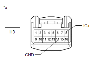
| 1. | CHECK HARNESS AND CONNECTOR (AIR CONDITIONING CONTROL ASSEMBLY - BATTERY AND BODY GROUND) |
| (a) Disconnect the air conditioning control assembly connector. |
|
(b) Measure the voltage according to the value(s) in the table below.
Standard Voltage:
| Tester Connection | Switch Condition | Specified Condition |
|---|---|---|
| I13-8 (IG+) - Body ground | Power switch off | Below 1 V |
| Power switch on (IG) | 11 to 14 V |
(c) Measure the resistance according to the value(s) in the table below.
Standard Resistance:
| Tester Connection | Condition | Specified Condition |
|---|---|---|
| I13-14 (GND) - Body ground | Always | Below 1 Ω |
| NG | .gif) | REPAIR OR REPLACE HARNESS OR CONNECTOR |
|
.gif)
| 2. | CHECK HARNESS AND CONNECTOR (AIR CONDITIONING CONTROL ASSEMBLY - AIR CONDITIONING AMPLIFIER ASSEMBLY) |
(a) Disconnect the I13 air conditioning control assembly connector.
(b) Disconnect the I50 air conditioning amplifier assembly connector.
(c) Measure the resistance according to the value(s) in the table below.
Standard Resistance:
| Tester Connection | Condition | Specified Condition |
|---|---|---|
| I13-6 (LIN1) - I50-37 (LIN1) | Always | Below 1 Ω |
| I13-6 (LIN1) or I50-37 (LIN1) - Body ground | Always | 10 kΩ or higher |
| NG | | REPAIR OR REPLACE HARNESS OR CONNECTOR |
|
| 3. | CHECK AIR CONDITIONING CONTROL ASSEMBLY |
(a) Replace the air conditioning control assembly.
Click here
(b) Check the air conditioning control assembly operates normally.
HINT:
Since the air conditioning control assembly cannot be inspected while it is removed from the vehicle, replace the air conditioning control assembly with a new or known good one and check that the condition returns to normal.
OK:
Air conditioning control assembly operation returns to normal.
| Result | Proceed to |
|---|---|
| OK | A |
| NG (When troubleshooting according to Problem Symptoms Table) | B |
| NG (When troubleshooting according to the DTC) | C |
| A | | END (AIR CONDITIONING CONTROL ASSEMBLY IS DEFECTIVE) |
| B | | PROCEED TO NEXT SUSPECTED AREA SHOWN IN PROBLEM SYMPTOMS TABLE |
| C | | REPLACE AIR CONDITIONING AMPLIFIER ASSEMBLY |
READ NEXT:
 Refrigerant Shortage (B14B8)
DESCRIPTION This DTC is stored if the amount of refrigerant in the air conditioning system is insufficient. The air conditioning amplifier assembly receives the ambient temperature signal, refrigerant
Hybrid Battery Voltage System Isolation Fault (P0AA6-611)
DESCRIPTION This DTC is stored if there is insulation malfunction in the high-voltage circuit in the air conditioning system. Possible causes are poor insulation in the compressor with motor assembly,
Lost Communication with ECM / PCM "A" (U0100-U0142,U0155,U0163,U0293)
DESCRIPTION DTC No. Detection Item DTC Detection Condition Trouble Area Memory Note U0100 Lost Communication with ECM / PCM "A" No communication with ECM
CAN communication sy
SEE MORE:
Problem Symptoms Table
PROBLEM SYMPTOMS TABLE NOTICE:
Recognition code registration is necessary when replacing the main body ECU (multiplex network body ECU).
If the main body ECU (multiplex network body ECU) is replaced, refer to Registration.
When replacing the combination meter assembly, always replace it with
Drive Motor "A" Position Sensor Circuit (P0A3F-243,P0A40-500,P0A41-245)
DTC SUMMARY MALFUNCTION DESCRIPTION These DTCs indicate the resolver output signal is abnormal. The cause of this malfunction may be one of the following: Area Main Malfunction Description Step Inverter low-voltage circuit The connectors are not connected properly 2 Resolver
