Lexus NX: HV Battery High-voltage Line Circuit
DESCRIPTION
The cause of the malfunction may be the HV battery high-voltage line circuit.
Check the continuity in the high-voltage line from the HV battery to the inverter.
Check the connection condition and for an open circuit in the frame wire from the service plug grip and HV battery to the inverter and perform a function check of the system main relay.
Related Parts Check| Area | Inspection | Step |
|---|---|---|
| High-voltage circuit from HV battery to inverter | Check connection condition and for open circuit. | 1, 4, 5 |
| Service plug grip | Check connection condition and for open circuit. | 2, 3 |
| System Main Relay | Check operation condition as relay. | 6, 7 |
SYSTEM DESCRIPTION
The HV battery high voltage is supplied to the inverter via the system main relay operation.
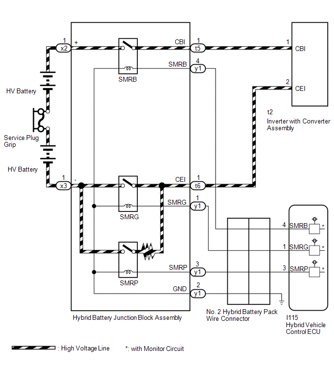
WIRING DIAGRAM
CAUTION / NOTICE / HINT
This step is referenced from the procedures for each DTC.
If the inspection results below are normal, perform the next procedure for the referenced DTC.
CAUTION:
- Before inspecting the high-voltage system or disconnecting the low voltage connector of the inverter with converter assembly, take safety precautions such as wearing insulated gloves and removing the service plug grip to prevent electrical shocks. After removing the service plug grip, put it in your pocket to prevent other technicians from accidentally reconnecting it while you are working on the high-voltage system.
-
After removing the service plug grip, wait for at least 10 minutes before touching any of the high-voltage connectors or terminals. After waiting for 10 minutes, check the voltage at the terminals in the inspection point in the inverter with converter assembly. The voltage should be 0 V before beginning work.
Click here
.gif)
HINT:
Waiting for at least 10 minutes is required to discharge the high-voltage capacitor inside the inverter with converter assembly.
NOTICE:
After turning the power switch off, waiting time may be required before disconnecting the cable from the negative (-) auxiliary battery terminal. Therefore, make sure to read the disconnecting the cable from the negative (-) auxiliary battery terminal notices before proceeding with work.
Click here
PROCEDURE
| 1. | CHECK INVERTER WITH CONVERTER ASSEMBLY (NO. 2 FRAME WIRE CONNECTION CONDITION) |
CAUTION:
Be sure to wear insulated gloves.
(a) Check that the service plug grip is not installed.
NOTICE:
After removing the service plug grip, do not turn the power switch on (READY), unless instructed by the repair manual because this may cause a malfunction.
| (b) Remove the inverter cover UPR from the inverter with converter assembly. |
|
.png)
| (c) Check that the bolt for the No. 2 frame wire is tightened to the specified torque, the No. 2 frame wire is connected securely, and there are no contact problems. Specified Condition: T = 8.0 N*m (82 kgf*cm, 71 in.*lbf) NOTICE: Make sure that the tightening torque of the bolt is between 6.4 and 9.6 N*m (65 and 98 kgf*cm, 57 and 85 in.*lbf). |
|
.png)
(d) Disconnect the No. 2 frame wire from the inverter with converter assembly.
(e) Check for arc marks at the bolt and terminals for the No. 2 frame wire.
| Result | Proceed to | |
|---|---|---|
| The terminals are connected securely and there are no contact problems. | There are no arc marks. | A |
| The terminals are not connected securely and there is a contact problem. | There are arc marks. | B |
| The terminals are not connected securely and there is a contact problem. | There are no arc marks. | C |
| The terminals are connected securely and there are no contact problems. | There are arc marks. | B |
(f) Reconnect the No. 2 frame wire.
(g) Install the inverter cover UPR.
| B | .gif) | REPLACE MALFUNCTIONING PARTS |
| C | | CONNECT SECURELY |
|
.gif)
| 2. | CHECK SERVICE PLUG GRIP (CONNECTION CONDITION) |
CAUTION:
Be sure to wear insulated gloves.
(a) Visually check the connection of the service plug grip to the HV battery. Remove the service plug grip and check for contamination.
OK:
Dirt or foreign matter has not entered the connectors, and there is no evidence of contamination.
(b) Install the service plug grip.
| NG | | REPLACE SERVICE PLUG GRIP |
|
| 3. | INSPECT SERVICE PLUG GRIP |
(a) Remove the service plug grip.
Click here
| (b) Measure the resistance according to the value(s) in the table below. Standard Resistance:
|
|
(c) Install the service plug grip.
| NG | | REPLACE SERVICE PLUG GRIP |
|
| 4. | CHECK HV BATTERY JUNCTION BLOCK ASSEMBLY (NO. 2 FRAME WIRE CONNECTION CONDITION) |
CAUTION:
Be sure to wear insulated gloves.
(a) Check that the service plug grip is not installed.
NOTICE:
After removing the service plug grip, do not turn the power switch on (READY), unless instructed by the repair manual because this may cause a malfunction.
(b) Remove the No. 2 hybrid vehicle battery shield reinforcement.
Click here
| (c) Check that the nuts for the No. 2 frame wire are tightened to the specified torque, the No. 2 frame wire is connected securely, and there are no contact problems. Specified Condition: T = 9.0 N*m (92 kgf*cm, 80 in.*lbf) |
|
.png)
(d) Check for arc marks on the terminals of the No. 2 frame wire.
| Result | Proceed to | |
|---|---|---|
| The terminals are connected securely and there are no contact problems. | There are no arc marks. | A |
| The terminals are not connected securely and there is a contact problem. | There are arc marks. | B |
| The terminals are not connected securely and there is a contact problem. | There are no arc marks. | C |
| The terminals are connected securely and there are no contact problems. | There are arc marks. | B |
(e) Install the No. 2 hybrid vehicle battery shield reinforcement.
| B | | REPLACE MALFUNCTIONING PARTS |
| C | | CONNECT SECURELY |
|
| 5. | CHECK NO. 2 FRAME WIRE |
CAUTION:
Be sure to wear insulated gloves.
(a) Check that the service plug grip is not installed.
NOTICE:
After removing the service plug grip, do not turn the power switch on (READY), unless instructed by the repair manual because this may cause a malfunction.
(b) Remove the No. 2 hybrid vehicle battery shield reinforcement.
Click here
| (c) Disconnect the No. 2 frame wire from the hybrid battery junction block assembly. |
|
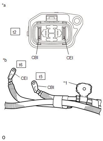
| (d) Remove the inverter cover UPR from the inverter with converter assembly. |
|
| (e) Disconnect the No. 2 frame wire from the inverter with converter assembly. |
|
| (f) Measure the resistance according to the value(s) in the table below. Standard Resistance:
|
|
(g) Using a megohmmeter set to 500 V, measure the resistance according to the value(s) in the table below.
NOTICE:
Be sure to set the megohmmeter to 500 V when performing this test. Using a setting higher than 500 V can result in damage to the component being inspected.
Standard Resistance:
| Tester Connection | Condition | Specified Condition |
|---|---|---|
| t5-1 (CBI) - Body ground and shield ground | Power switch off | 10 MΩ or higher |
| t6-1 (CEI) - Body ground and shield ground | Power switch off | 10 MΩ or higher |
| t5-1 (CBI) - t6-1 (CEI) | Power switch off | 10 MΩ or higher |
(h) Reconnect the No. 2 frame wire to the hybrid battery junction block assembly.
(i) Reconnect the No. 2 frame wire to the inverter with converter assembly.
(j) Install the inverter cover UPR.
(k) Install the No. 2 hybrid vehicle battery shield reinforcement.
| NG | | REPLACE NO. 2 FRAME WIRE |
|
| 6. | CHECK HV BATTERY JUNCTION BLOCK ASSEMBLY (SMRB) |
CAUTION:
Be sure to wear insulated gloves.
(a) Check that the service plug grip is not installed.
NOTICE:
After removing the service plug grip, do not turn the power switch on (READY), unless instructed by the repair manual because this may cause a malfunction.
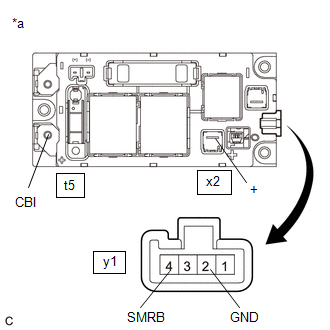
(b) Remove the hybrid battery junction block assembly.
Click here
| (c) Measure the resistance according to the value(s) in the table below. Standard Resistance:
|
|
(d) Measure the resistance according to the value(s) in the table below.
Standard Resistance:
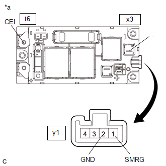
| Tester Connection | Condition | Specified Condition |
|---|---|---|
| y1-4 (SMRB) - y1-2 (GND) | -40 to 80°C (-40 to 176°F) | 20.6 to 40.8 Ω |
(e) Install the hybrid battery junction block assembly.
| NG | | REPLACE HV BATTERY JUNCTION BLOCK ASSEMBLY |
|
| 7. | CHECK HV BATTERY JUNCTION BLOCK ASSEMBLY (SMRG) |
CAUTION:
Be sure to wear insulated gloves.
(a) Check that the service plug grip is not installed.
NOTICE:
After removing the service plug grip, do not turn the power switch on (READY), unless instructed by the repair manual because this may cause a malfunction.
(b) Remove the hybrid battery junction block assembly.
Click here
| (c) Measure the resistance according to the value(s) in the table below. Standard Resistance:
|
|
(d) Measure the resistance according to the value(s) in the table below.
Standard Resistance:
| Tester Connection | Condition | Specified Condition |
|---|---|---|
| y1-1 (SMRG) - y1-2 (GND) | -40 to 80°C (-40 to 176°F) | 20.6 to 40.8 Ω |
(e) Install the hybrid battery junction block assembly.
| OK | | HV BATTERY HIGH-VOLTAGE LINE CIRCUIT NORMAL (PERFORM NEXT STEP FOR REFERENCED DTC) |
| NG | | REPLACE HV BATTERY JUNCTION BLOCK ASSEMBLY |
READ NEXT:
 Cooling System
DESCRIPTION The cause of the malfunction may be the cooling system. Check whether the grille is blocked, whether coolant is leaking, the HV radiator fan operating condition and whether coolant has fro
Hybrid Vehicle Control Ecu
ComponentsCOMPONENTS ILLUSTRATION *1 ECU INTEGRATION BOX RH *2 GLOVE COMPARTMENT DOOR ASSEMBLY *3 HYBRID VEHICLE CONTROL ECU *4 NO. 2 INSTRUMENT PANEL UNDER COVER SUB-ASSEMBLY
SEE MORE:
Hybrid system precautions
Take care when handling the hybrid system, as it is a high voltage
system
(about 650 V at maximum) as well as contains parts that become extremely
hot when the hybrid system is operating. Obey the warning labels attached to
the vehicle.
System components
The illustration is an example for e
Drive Motor "A" Torque Delivered Performance (P0C19-306)
DTC SUMMARY MALFUNCTION DESCRIPTION This DTC indicates that the motor torque execution value does not correspond to the torque command value sent from the hybrid vehicle control ECU to the motor. The cause of this malfunction may be one of the following: Area Main Malfunction Description Step
