Lexus NX: Lost Communication with Haptic Device (B1323-B1326)
DESCRIPTION
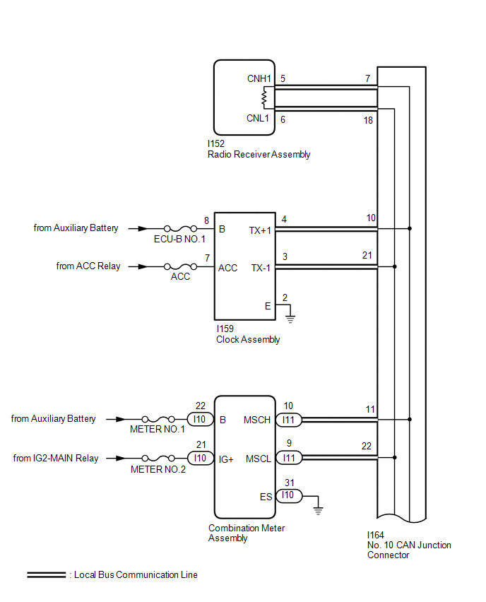
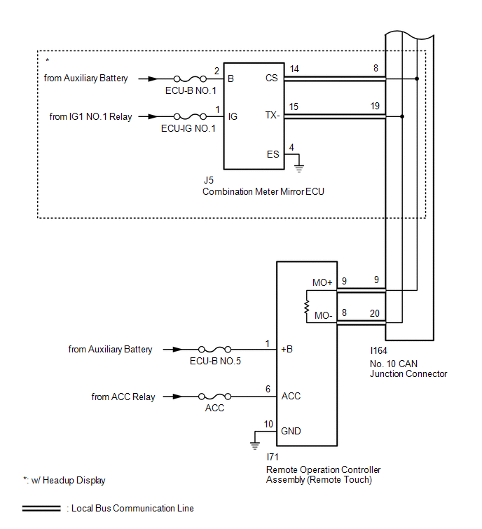
These DTCs are stored when communication between the radio receiver assembly and remote operation controller assembly (remote touch), combination meter assembly, combination meter mirror ECU* or clock assembly is not possible.
- *: w/ Headup Display
| DTC No. | Detection Item | DTC Detection Condition | Trouble Area |
|---|---|---|---|
| B1323 | Lost Communication with Haptic Device | CAN reception error |
|
| B1324 | Lost Communication with Meter | CAN reception error |
|
| B1325 | Lost Communication with HUD | CAN reception error |
|
| B1326 | Lost Communication with Clock Device (Local-CAN) | CAN reception error |
|
HINT:
The radio receiver assembly is the master unit.
WIRING DIAGRAM
CAUTION / NOTICE / HINT
NOTICE:
-
When replacing the radio receiver assembly, always replace it with a new one.
If a radio receiver assembly which was installed to another vehicle is used, the following may occur:
- A communication malfunction DTC may be stored.
- The radio receiver assembly may not operate normally.
- Inspect the fuses for circuits related to this system before performing the following procedure.
-
After turning the power switch off, waiting time may be required before disconnecting the cable from the negative (-) auxiliary battery terminal.
Click here
.gif)
-
When disconnecting and reconnecting the auxiliary battery.
Click here
HINT:
When disconnecting and reconnecting the auxiliary battery, there is an automatic learning function that completes learning when the respective system is used.
Click here
HINT:
- B1323, B1324, B1325 and B1326 will not continue to output when clear DTC is performed even if the malfunction continues.
-
Depending on the parts that are replaced during vehicle inspection or maintenance, performing initialization, registration or calibration may be needed. Refer to Precaution for Navigation System.
Click here
PROCEDURE
| 1. | CHECK DTC |
(a) Check for DTCs.
Click here
| Result | Proceed to |
|---|---|
| DTCs B1323, B1324, B1325* and B1326 are output | A |
| DTC B1323 is output | B |
| DTC B1324 is output | C |
| DTCs B1325 is output* | D |
| DTC B1326 is output | E |
| B | .gif) | GO TO STEP 3 |
| C | | GO TO STEP 16 |
| D | | GO TO STEP 20 |
| E | | GO TO STEP 24 |
|
.gif)
| 2. | CHECK LOCAL BUS |
| (a) Disconnect the cable from the negative (-) auxiliary battery terminal. |
|
(b) Measure the resistance according to the value(s) in the table below.
Standard Resistance:
| Tester Connection | Condition | Specified Condition |
|---|---|---|
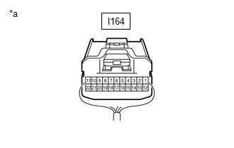
| I164-7 - I164-18 | Cable disconnected from negative (-) auxiliary battery terminal | 54 to 69 Ω |
| Result | Proceed to |
|---|---|
| OK | A |
| NG (Below 54 Ω) | B |
| NG (70 Ω or higher) | C |
| A | | USE SIMULATION METHOD TO CHECK |
| B | | GO TO STEP 5 |
| C | | GO TO STEP 18 |
| 3. | CHECK HARNESS AND CONNECTOR (REMOTE OPERATION CONTROLLER ASSEMBLY [REMOTE TOUCH] POWER SOURCE) |
| (a) Disconnect the remote operation controller assembly (remote touch) connector. |
|
.png)
(b) Measure the resistance according to the value(s) in the table below.
Standard Resistance:
| Tester Connection | Condition | Specified Condition |
|---|---|---|
| I71-10 (GND) - Body ground | Always | Below 1 Ω |
(c) Measure the voltage according to the value(s) in the table below.
Standard Voltage:
| Tester Connection | Condition | Specified Condition |
|---|---|---|
| I71-1 (+B) - Body ground | Power switch off | 11 to 14 V |
| I71-6 (ACC) - Body ground | Power switch on (ACC) | 11 to 14 V |
| NG | | REPAIR OR REPLACE HARNESS OR CONNECTOR |
|
| 4. | CHECK HARNESS AND CONNECTOR (REMOTE OPERATION CONTROLLER ASSEMBLY [REMOTE TOUCH] - NO. 10 CAN JUNCTION CONNECTOR) |
| (a) Disconnect the cable from the negative (-) auxiliary battery terminal. |
|
.png)
(b) Disconnect the remote operation controller assembly (remote touch) connector.
(c) Measure the resistance according to the value(s) in the table below.
Standard Resistance:
| Tester Connection | Condition | Specified Condition |
|---|---|---|
| I71-9 (MO+) - I71-8 (MO-) | Cable disconnected from negative (-) auxiliary battery terminal | 108 to 132 Ω |
| OK | | REPLACE REMOTE OPERATION CONTROLLER ASSEMBLY (REMOTE TOUCH) |
| NG | | REPAIR OR REPLACE HARNESS OR CONNECTOR |
| 5. | CHECK HARNESS AND CONNECTOR (NO. 10 CAN JUNCTION CONNECTOR - RADIO RECEIVER ASSEMBLY) |
(a) Disconnect the No. 10 CAN junction connector.
| (b) Measure the resistance according to the value(s) in the table below. Standard Resistance:
|
|
.png)
| NG | | GO TO STEP 11 |
|
| 6. | CHECK HARNESS AND CONNECTOR (NO. 10 CAN JUNCTION CONNECTOR - REMOTE OPERATION CONTROLLER ASSEMBLY [REMOTE TOUCH]) |
| (a) Disconnect the No. 10 CAN junction connector. |
|
.png)
(b) Measure the resistance according to the value(s) in the table below.
Standard Resistance:
| Tester Connection | Condition | Specified Condition |
|---|---|---|
| I164-9 - I164-20 | Cable disconnected from negative (-) auxiliary battery terminal | 108 to 132 Ω |
| NG | | GO TO STEP 12 |
|
| 7. | CHECK HARNESS AND CONNECTOR (NO. 10 CAN JUNCTION CONNECTOR - COMBINATION METER ASSEMBLY) |
| (a) Disconnect the No. 10 CAN junction connector. |
|
.png)
(b) Measure the resistance according to the value(s) in the table below.
Standard Resistance:
| Tester Connection | Condition | Specified Condition |
|---|---|---|
| I164-11 - I164-22 | Cable disconnected from negative (-) auxiliary battery terminal | 200 Ω or higher |
| NG | | GO TO STEP 13 |
|
| 8. | CHECK VEHICLE TYPE |
(a) Check the vehicle type.
| Result | Proceed to |
|---|---|
| w/ Headup Display | A |
| w/o Headup Display | B |
| B | | GO TO STEP 10 |
|
| 9. | CHECK HARNESS AND CONNECTOR (NO. 10 CAN JUNCTION CONNECTOR - COMBINATION METER MIRROR ECU) |
(a) Disconnect the No. 10 CAN junction connector.
| (b) Measure the resistance according to the value(s) in the table below. Standard Resistance:
|
|
| NG | | GO TO STEP 14 |
|
| 10. | CHECK HARNESS AND CONNECTOR (NO. 10 CAN JUNCTION CONNECTOR - CLOCK ASSEMBLY) |
| (a) Disconnect the No. 10 CAN junction connector. |
|
(b) Measure the resistance according to the value(s) in the table below.
Standard Resistance:
| Tester Connection | Condition | Specified Condition |
|---|---|---|
| I164-10 - I164-21 | Cable disconnected from negative (-) auxiliary battery terminal | 200 Ω or higher |
| OK | | REPLACE NO. 10 CAN JUNCTION CONNECTOR |
| NG | | GO TO STEP 15 |
| 11. | CHECK HARNESS AND CONNECTOR (RADIO RECEIVER ASSEMBLY - NO. 10 CAN JUNCTION CONNECTOR) |
| (a) Disconnect the radio receiver assembly connector. |
|
.png)
(b) Measure the resistance according to the value(s) in the table below.
Standard Resistance:
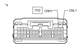
| Tester Connection | Condition | Specified Condition |
|---|---|---|
| I152-5 (CNH1) - I152-6 (CNL1) | Cable disconnected from negative (-) auxiliary battery terminal | 108 to 132 Ω |
| OK | | REPLACE RADIO RECEIVER ASSEMBLY |
| NG | | REPAIR OR REPLACE HARNESS OR CONNECTOR |
| 12. | CHECK HARNESS AND CONNECTOR (REMOTE OPERATION CONTROLLER ASSEMBLY [REMOTE TOUCH] - NO. 10 CAN JUNCTION CONNECTOR) |
| (a) Disconnect the remote operation controller assembly (remote touch) connector. |
|
.png)
(b) Measure the resistance according to the value(s) in the table below.
Standard Resistance:
| Tester Connection | Condition | Specified Condition |
|---|---|---|
| I71-9 (MO+) - I71-8 (MO-) | Cable disconnected from negative (-) auxiliary battery terminal | 108 to 132 Ω |
| OK | | REPLACE REMOTE OPERATION CONTROLLER ASSEMBLY (REMOTE TOUCH) |
| NG | | REPAIR OR REPLACE HARNESS OR CONNECTOR |
| 13. | CHECK HARNESS AND CONNECTOR (COMBINATION METER ASSEMBLY - NO. 10 CAN JUNCTION CONNECTOR) |
| (a) Disconnect the combination meter assembly connector. |
|
.png)
(b) Measure the resistance according to the value(s) in the table below.
Standard Resistance:
| Tester Connection | Condition | Specified Condition |
|---|---|---|
| I11-10 (MSCH) - I11-9 (MSCL) | Cable disconnected from negative (-) auxiliary battery terminal | 54 to 69 Ω |
| OK | | REPLACE COMBINATION METER ASSEMBLY |
| NG | | REPAIR OR REPLACE HARNESS OR CONNECTOR |
| 14. | CHECK HARNESS AND CONNECTOR (COMBINATION METER MIRROR ECU - NO. 10 CAN JUNCTION CONNECTOR) |
| (a) Disconnect the combination meter mirror ECU connector. |
|
.png)
(b) Measure the resistance according to the value(s) in the table below.
Standard Resistance:
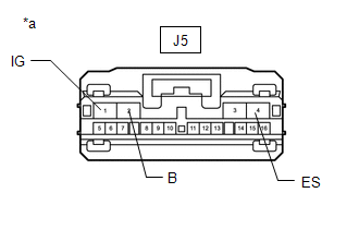
| Tester Connection | Condition | Specified Condition |
|---|---|---|
| J5-14 (CS) - J5-15 (TX-) | Cable disconnected from negative (-) auxiliary battery terminal | 54 to 69 Ω |
| OK | | REPLACE COMBINATION METER MIRROR ECU |
| NG | | REPAIR OR REPLACE HARNESS OR CONNECTOR |
| 15. | CHECK HARNESS AND CONNECTOR (CLOCK ASSEMBLY - NO. 10 CAN JUNCTION CONNECTOR) |
| (a) Disconnect the clock assembly connector. |
|
(b) Measure the resistance according to the value(s) in the table below.
Standard Resistance:
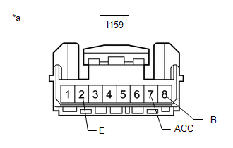
| Tester Connection | Condition | Specified Condition |
|---|---|---|
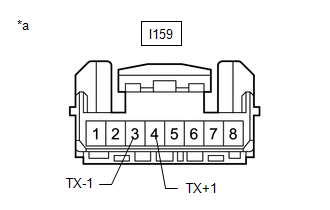
| I159-4 (TX+1) - I159-3 (TX-1) | Cable disconnected from negative (-) auxiliary battery terminal | 54 to 69 Ω |
| OK | | REPLACE CLOCK ASSEMBLY |
| NG | | REPAIR OR REPLACE HARNESS OR CONNECTOR |
| 16. | CHECK HARNESS AND CONNECTOR (COMBINATION METER ASSEMBLY POWER SOURCE) |
| (a) Disconnect the combination meter assembly connector. |
|
.png)
(b) Measure the resistance according to the value(s) in the table below.
Standard Resistance:
| Tester Connection | Condition | Specified Condition |
|---|---|---|
| I10-31 (ES) - Body ground | Always | Below 1 Ω |
(c) Measure the voltage according to the value(s) in the table below.
Standard Voltage:
| Tester Connection | Condition | Specified Condition |
|---|---|---|
| I10-22 (B) - Body ground | Power switch off | 11 to 14 V |
| I10-21 (IG+) - Body ground | Power switch on (IG) | 11 to 14 V |
| NG | | REPAIR OR REPLACE HARNESS OR CONNECTOR |
|
| 17. | CHECK HARNESS AND CONNECTOR (COMBINATION METER ASSEMBLY - NO. 10 CAN JUNCTION CONNECTOR) |
| (a) Disconnect the cable from the negative (-) auxiliary battery terminal. |
|
.png)
(b) Disconnect the combination meter assembly connector.
(c) Measure the resistance according to the value(s) in the table below.
Standard Resistance:
| Tester Connection | Condition | Specified Condition |
|---|---|---|
| I11-10 (MSCH) - I11-9 (MSCL) | Cable disconnected from negative (-) auxiliary battery terminal | 54 to 69 Ω |
| OK | | REPLACE COMBINATION METER ASSEMBLY |
| NG | | REPAIR OR REPLACE HARNESS OR CONNECTOR |
| 18. | CHECK HARNESS AND CONNECTOR (NO. 10 CAN JUNCTION CONNECTOR - RADIO RECEIVER ASSEMBLY) |
(a) Disconnect the cable from the negative (-) auxiliary battery terminal.
(b) Disconnect the No. 10 CAN junction connector.
| (c) Measure the resistance according to the value(s) in the table below. Standard Resistance:
|
|
| NG | | GO TO STEP 22 |
|
| 19. | CHECK HARNESS AND CONNECTOR (NO. 10 CAN JUNCTION CONNECTOR - REMOTE OPERATION CONTROLLER ASSEMBLY [REMOTE TOUCH]) |
(a) Disconnect the cable from the negative (-) auxiliary battery terminal.
(b) Disconnect the No. 10 CAN junction connector.
| (c) Measure the resistance according to the value(s) in the table below. Standard Resistance:
|
|
| OK | | REPLACE NO. 10 CAN JUNCTION CONNECTOR |
| NG | | GO TO STEP 23 |
| 20. | CHECK HARNESS AND CONNECTOR (COMBINATION METER MIRROR ECU POWER SOURCE) |
| (a) Disconnect the combination meter mirror ECU connector. |
|
(b) Measure the resistance according to the value(s) in the table below.
Standard Resistance:
| Tester Connection | Condition | Specified Condition |
|---|---|---|
| J5-4 (ES) - Body ground | Always | Below 1 Ω |
(c) Measure the voltage according to the value(s) in the table below.
Standard Voltage:
| Tester Connection | Condition | Specified Condition |
|---|---|---|
| J5-2 (B) - Body ground | Power switch off | 11 to 14 V |
| J5-1 (IG) - Body ground | Power switch on (IG) | 11 to 14 V |
| NG | | REPAIR OR REPLACE HARNESS OR CONNECTOR |
|
| 21. | CHECK HARNESS AND CONNECTOR (COMBINATION METER MIRROR ECU - NO. 10 CAN JUNCTION CONNECTOR) |
| (a) Disconnect the cable from the negative (-) auxiliary battery terminal. |
|
(b) Disconnect the combination meter mirror ECU connector.
(c) Measure the resistance according to the value(s) in the table below.
Standard Resistance:
| Tester Connection | Condition | Specified Condition |
|---|---|---|
| J5-14 (CS) - J5-15 (TX-) | Cable disconnected from negative (-) auxiliary battery terminal | 54 to 69 Ω |
| OK | | REPLACE COMBINATION METER MIRROR ECU |
| NG | | REPAIR OR REPLACE HARNESS OR CONNECTOR |
| 22. | CHECK HARNESS AND CONNECTOR (RADIO RECEIVER ASSEMBLY - NO. 10 CAN JUNCTION CONNECTOR) |
| (a) Disconnect the radio receiver assembly connector. |
|
(b) Measure the resistance according to the value(s) in the table below.
Standard Resistance:
| Tester Connection | Condition | Specified Condition |
|---|---|---|
| I152-5 (CNH1) - I152-6 (CNL1) | Cable disconnected from negative (-) auxiliary battery terminal | 108 to 132 Ω |
| OK | | REPLACE RADIO RECEIVER ASSEMBLY |
| NG | | REPAIR OR REPLACE HARNESS OR CONNECTOR |
| 23. | CHECK HARNESS AND CONNECTOR (REMOTE OPERATION CONTROLLER ASSEMBLY [REMOTE TOUCH] - NO. 10 CAN JUNCTION CONNECTOR) |
| (a) Disconnect the remote operation controller assembly (remote touch) connector. |
|
(b) Measure the resistance according to the value(s) in the table below.
Standard Resistance:
| Tester Connection | Condition | Specified Condition |
|---|---|---|
| I71-9 (MO+) - I71-8 (MO-) | Cable disconnected from negative (-) auxiliary battery terminal | 108 to 132 Ω |
| OK | | REPLACE REMOTE OPERATION CONTROLLER ASSEMBLY (REMOTE TOUCH) |
| NG | | REPAIR OR REPLACE HARNESS OR CONNECTOR |
| 24. | CHECK HARNESS AND CONNECTOR (CLOCK ASSEMBLY POWER SOURCE) |
| (a) Disconnect the clock assembly connector. |
|
(b) Measure the resistance according to the value(s) in the table below.
Standard Resistance:
| Tester Connection | Condition | Specified Condition |
|---|---|---|
| I159-2 (E) - Body ground | Always | Below 1 Ω |
(c) Measure the voltage according to the value(s) in the table below.
Standard Voltage:
| Tester Connection | Condition | Specified Condition |
|---|---|---|
| I159-8 (B) - Body ground | Power switch off | 11 to 14 V |
| I159-7 (ACC) - Body ground | Power switch on (ACC) | 11 to 14 V |
| NG | | REPAIR OR REPLACE HARNESS OR CONNECTOR |
|
| 25. | CHECK HARNESS AND CONNECTOR (CLOCK ASSEMBLY - NO. 10 CAN JUNCTION CONNECTOR) |
| (a) Disconnect the cable from the negative (-) auxiliary battery terminal. |
|
(b) Disconnect the clock assembly connector.
(c) Measure the resistance according to the value(s) in the table below.
Standard Resistance:
| Tester Connection | Condition | Specified Condition |
|---|---|---|
| I159-4 (TX+1) - I159-3 (TX-1) | Cable disconnected from negative (-) auxiliary battery terminal | 54 to 69 Ω |
| OK | | REPLACE CLOCK ASSEMBLY |
| NG | | REPAIR OR REPLACE HARNESS OR CONNECTOR |
READ NEXT:
 NTSC Disconnected (from Park Assist/Monitoring ECU) (B1535,C1622)
DESCRIPTION This DTC is stored if the radio receiver assembly judges that the signals or signal lines between the television camera assembly and the multi-display assembly are not normal as a result o
GVIF Disconnected (from Extension Module to H/U) (B153A)
DESCRIPTION DTC No. Detection Item DTC Detection Condition Trouble Area B153A GVIF Disconnected (from Extension Module to H/U) GVIF disconnected (from navigation ECU to radio receiver
Extension Module Disconnected 2 (B1543)
DESCRIPTION If the radio receiver assembly cannot detect the navigation ECU for a certain period of time (90 seconds) after the power switch is turned on (ACC) and the radio receiver assembly confirms
SEE MORE:
Heated Oxygen Sensor
ComponentsCOMPONENTS ILLUSTRATION *1 FRONT EXHAUST PIPE SUB-ASSEMBLY *2 HEATED OXYGEN SENSOR *3 COMPRESSION SPRING *4 GASKET N*m (kgf*cm, ft.*lbf): Specified torque * For use with SST ● Non-reusable part - - RemovalREMOVAL PROCEDURE 1. REMOVE FRONT EXH
Dtc Check / Clear
DTC CHECK / CLEAR CHECK FOR DTC (a) Connect the Techstream to the DLC3. (b) Turn the power switch on (IG). (c) Turn the Techstream on. (d) Enter the following menus: Body Electrical / AFS / Trouble Codes. Body Electrical > AFS > Trouble Codes (e) Check for DTCs. CLEAR DTC (a) Connect the Techs
