Lexus NX: Extension Module Disconnected 2 (B1543)
DESCRIPTION
If the radio receiver assembly cannot detect the navigation ECU for a certain period of time (90 seconds) after the power switch is turned on (ACC) and the radio receiver assembly confirms that the information is missing by checking past navigation ECU recognition information (registered information), this DTC will be stored.
HINT:
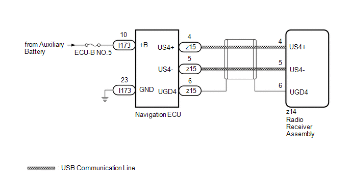
The Navigation system uses USB communication between devices. If an open, short, short to +B or short to ground occurs in the USB circuit, communication is interrupted and the Navigation system will not operate normally.
| DTC No. | Detection Item | DTC Detection Condition | Trouble Area |
|---|---|---|---|
| B1543 | Extension Module Disconnected 2 | Navigation ECU disconnected |
|
HINT:
This DTC may be stored due to environmental reasons such as electrical noise or interference.
WIRING DIAGRAM
CAUTION / NOTICE / HINT
NOTICE:
- Inspect the fuses for circuits related to this system before performing the following procedure.
-
When replacing the radio receiver assembly or navigation ECU, always replace it with a new one.
If a radio receiver assembly or navigation ECU which was installed to another vehicle is used, the following may occur:
- A communication malfunction DTC may be stored.
- The radio receiver assembly or navigation ECU may not operate normally.
HINT:
Depending on the parts that are replaced during vehicle inspection or maintenance, performing initialization, registration or calibration may be needed. Refer to Precaution for Navigation System.
Click here .gif)
PROCEDURE
| 1. | CHECK MAP SCREEN |
(a) Turn the power switch on (ACC) and wait for 90 seconds.
(b) Press the "MAP" switch and check that the map screen is displayed normally.
| Result | Proceed to |
|---|---|
| Map screen is displayed normally | A |
| Map screen is not displayed normally | B |
HINT:
- This DTC may be stored due to environmental reasons such as electrical noise or interference.
- Clear past DTCs when the map screen is displayed normally. (Codes stored due to past environmental factors)
| A | .gif) | USE SIMULATION METHOD TO CHECK |
|
.gif)
| 2. | CHECK DTC |
(a) Clear the DTCs.
Click here
(b) Turn the power switch off.
(c) Turn the power switch on (IG) and wait for 90 seconds.
(d) Recheck for DTCs and check that no DTCs are output.
Click here
OK:
No DTCs are output.
| OK | | USE SIMULATION METHOD TO CHECK |
|
| 3. | CHECK HARNESS AND CONNECTOR (NAVIGATION ECU - BATTERY AND BODY GROUND) |
| (a) Disconnect the navigation ECU connector. |
|
(b) Measure the resistance according to the value(s) in the table below.
Standard Resistance:
| Tester Connection | Condition | Specified Condition |
|---|---|---|
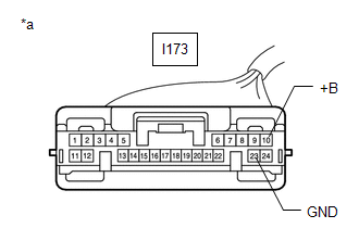
| I173-23 (GND) - Body ground | Always | Below 1 Ω |
(c) Measure the voltage according to the value(s) in the table below.
Standard Voltage:
| Tester Connection | Condition | Specified Condition |
|---|---|---|
| I173-10 (+B) - Body ground | Power switch off | 11 to 14 V |
| NG | | REPAIR OR REPLACE HARNESS OR CONNECTOR |
|
| 4. | CHECK HARNESS AND CONNECTOR (RADIO RECEIVER ASSEMBLY - NAVIGATION ECU) |
| (a) Disconnect the z15 navigation ECU connector. |
|
(b) Disconnect the z14 radio receiver assembly connector.
(c) Measure the resistance according to the value(s) in the table below.
Standard Resistance:
| Tester Connection | Condition | Specified Condition |
|---|---|---|
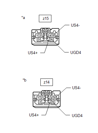
| z15-4 (US4+) - z14-4 (US4+) | Always | Below 1 Ω |
| z15-5 (US4-) - z14-5 (US4-) | Always | Below 1 Ω |
| z15-6 (UGD4) - z14-6 (UGD4) | Always | Below 1 Ω |
| NG | | REPAIR OR REPLACE HARNESS AND CONNECTOR |
|
| 5. | REPLACE NAVIGATION ECU |
(a) Replace the navigation ECU with a new one.
Click here
|
| 6. | CHECK DTC |
(a) Clear the DTCs.
Click here
(b) Turn the power switch off.
(c) Turn the power switch on (IG) and wait for 90 seconds.
(d) Recheck for DTCs and check that no DTCs are output.
Click here
OK:
No DTCs are output.
| OK | | END (NAVIGATION ECU IS DEFECTIVE) |
| NG | | REPLACE RADIO RECEIVER ASSEMBLY |
READ NEXT:
 HD Radio Tuner Malfunction (B1551,B15A0,B15B3,B15B5,B15B7,B15BA,B15F9)
DESCRIPTION These DTCs are stored when a malfunction occurs in the radio receiver assembly DTC No. Detection Item DTC Detection Condition Trouble Area B1551 HD Radio Tuner Malfunction
Extension Module Malfunction 2 (B1556)
DESCRIPTION These DTCs are stored when a malfunction occurs in the Navigation ECU. DTC No. Detection Item DTC Detection Condition Trouble Area B1556 Extension Module Malfunction 2 Whe
Touch Pad Sensor Malfunction (B1559)
DESCRIPTION This DTC is stored if the remote operation controller assembly (remote touch) detects a malfunction in itself, such as internal hardware failure or touch pad sensor malfunction. DTC No.
SEE MORE:
How To Proceed With Troubleshooting
CAUTION / NOTICE / HINT HINT:
Use this procedure to troubleshoot the immobiliser system.
*: Use the Techstream.
PROCEDURE 1. VEHICLE BROUGHT TO WORKSHOP
NEXT 2. CUSTOMER PROBLEM ANALYSIS HINT:
In troubleshooting, confirm that the problem symptoms have be
Components
COMPONENTS ILLUSTRATION *1 DECK FLOOR BOX LH *2 NO. 3 DECK BOARD SUB-ASSEMBLY *3 REAR DECK FLOOR BOX *4 NEGATIVE AUXILIARY BATTERY TERMINAL N*m (kgf*cm, ft.*lbf): Specified torque - - ILLUSTRATION *1 ECU INTEGRATION BOX RH *2 GLOVE COMPARTMENT DOOR ASSEMBL
