Lexus NX: Navigation Ecu
Lexus NX Service Manual / Audio & Visual & Telematics / Navigation / Multi Info Display / Navigation Ecu
Components
COMPONENTS
ILLUSTRATION
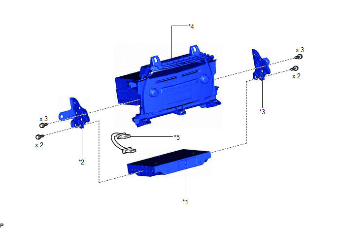
| *1 | NAVIGATION ECU | *2 | NO. 1 RADIO BRACKET |
| *3 | NO. 2 RADIO BRACKET | *4 | RADIO RECEIVER ASSEMBLY WITH BRACKET |
| *5 | NAVIGATION WIRE | - | - |
Removal
REMOVAL
PROCEDURE
1. REMOVE RADIO RECEIVER ASSEMBLY WITH BRACKET
Click here .gif)
2. REMOVE NO. 1 RADIO BRACKET
Click here
3. REMOVE NO. 2 RADIO BRACKET
Click here
4. REMOVE NAVIGATION ECU
| (a) Disconnect the connectors and remove the navigation wire. |
|
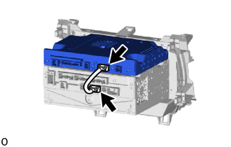
(b) Remove the navigation ECU.
Installation
INSTALLATION
PROCEDURE
1. INSTALL NAVIGATION ECU
| (a) Connect the connectors and install a navigation ECU in the mounting location. |
|
.png)
2. INSTALL NO. 1 RADIO BRACKET
Click here .gif)
3. INSTALL NO. 2 RADIO BRACKET
Click here
4. INSTALL RADIO RECEIVER ASSEMBLY WITH BRACKET
Click here
READ NEXT:
 Precaution
PRECAUTION PRECAUTION FOR DISCONNECTING CABLE FROM NEGATIVE AUXILIARY BATTERY TERMINAL NOTICE: After the power switch is turned off, the radio receiver assembly records various types of memory and set
Parts Location
PARTS LOCATION ILLUSTRATION *A w/ Parking Assist Monitor System *B w/ Panoramic View Monitor System *1 NO. 2 ENGINE ROOM RELAY BLOCK - DCM FUSE (w/ Manual [SOS] Switch) - ECU-B NO.1 FU
SEE MORE:
XM Tuner Antenna Disconnected (B15FE,B15FF)
DESCRIPTION These DTCs are stored when a malfunction occurs in the roof antenna assembly which is connected to the radio receiver assembly. DTC No. Detection Item DTC Detection Condition Trouble Area B15FE XM Tuner Antenna Disconnected The roof antenna assembly is not connected.
How To Proceed With Troubleshooting
CAUTION / NOTICE / HINT HINT:
Use the following procedure to troubleshoot the headup display system.
*: Use the Techstream.
PROCEDURE 1. VEHICLE BROUGHT TO WORKSHOP
NEXT 2. CUSTOMER PROBLEM ANALYSIS
NEXT 3. INSPECT AUXILIARY BATTE
© 2016-2026 Copyright www.lexunx.com
