Lexus NX: No. 2 Clearance Warning Buzzer Circuit
DESCRIPTION
This circuit consists of the No. 2 clearance warning buzzer and clearance warning ECU assembly. An ECU-excited type buzzer is used. The ECU operates the buzzers using a sound pattern that changes depending on the distance to the obstacle.
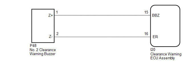
WIRING DIAGRAM
PROCEDURE
| 1. | PERFORM ACTIVE TEST USING TECHSTREAM |
(a) Connect the Techstream to the DLC3.
(b) Turn the power switch on (IG).
(c) Turn the Techstream on.
(d) Enter the following menus: Body Electrical / Advanced Parking Guidance/ICS/Intuitive P/A / Active Test.
(e) Check that the buzzer operates by performing the Active Test.
Body Electrical > Advanced Parking Guidance/ICS/Intuitive P/A > Active Test| Tester Display | Measurement Item | Control Range | Diagnostic Note |
|---|---|---|---|
| Rear Buzzer | No. 2 clearance warning buzzer | Operate or Stop | Confirm that the vehicle is stopped and the power switch is on (IG) |
| Tester Display |
|---|
| Rear Buzzer |
OK:
The No. 2 clearance warning buzzer sounds.
| OK | .gif) | PROCEED TO NEXT SUSPECTED AREA SHOWN IN PROBLEM SYMPTOMS TABLE |
|
.gif)
| 2. | CHECK HARNESS AND CONNECTOR (CLEARANCE WARNING ECU ASSEMBLY - NO. 2 CLEARANCE WARNING BUZZER) |
(a) Disconnect the I20 clearance warning ECU assembly connector.
(b) Disconnect the P48 No. 2 clearance warning buzzer connector.
(c) Measure the resistance according to the value(s) in the table below.
Standard Resistance:
| Tester Connection | Condition | Specified Condition |
|---|---|---|
| I20-15 (BBZ) - P48-1 (Z+) | Always | Below 1 Ω |
| I20-16 (ER) - P48-2 (Z-) | Always | Below 1 Ω |
| I20-15 (BBZ) or P48-1 (Z+) - Body ground | Always | 10 kΩ or higher |
| I20-16 (ER) or P48-2 (Z-) - Body ground | Always | 10 kΩ or higher |
| NG | | REPAIR OR REPLACE HARNESS OR CONNECTOR |
|
| 3. | REPLACE NO. 2 CLEARANCE WARNING BUZZER |
(a) Replace the No. 2 clearance warning buzzer with a new or known good one.
Click here .gif)
|
| 4. | PERFORM ACTIVE TEST USING TECHSTREAM |
(a) Connect the Techstream to the DLC3.
(b) Turn the power switch on (IG).
(c) Turn the Techstream on.
(d) Enter the following menus: Body Electrical / Advanced Parking Guidance/ICS/Intuitive P/A / Active Test.
(e) Check that the buzzer operates by performing the Active Test.
Body Electrical > Advanced Parking Guidance/ICS/Intuitive P/A > Active Test| Tester Display | Measurement Item | Control Range | Diagnostic Note |
|---|---|---|---|
| Rear Buzzer | No. 2 clearance warning buzzer | Operate or Stop | Confirm that the vehicle is stopped and the power switch is on (IG) |
| Tester Display |
|---|
| Rear Buzzer |
OK:
The No. 2 clearance warning buzzer sounds.
| OK | | END (NO. 2 CLEARANCE WARNING BUZZER WAS DEFECTIVE) |
| NG | | REPLACE CLEARANCE WARNING ECU ASSEMBLY |
READ NEXT:
 Sensor Frozen Indication (Dirty or Frozen)
DESCRIPTION When the ultrasonic sensor is dirty or frozen, "Parking Assist Unavailable Clean Parking Assist Sensor" is displayed on the multi-information display in the combination meter assembly. PRO
Panoramic View Monitor Switch
InspectionINSPECTION PROCEDURE 1. INSPECT NO. 2 COMBINATION SWITCH ASSEMBLY (for Type A) (a) Remove the No. 2 combination switch assembly. Click here (b) Measure the resistance according to the
SEE MORE:
Windshield wipers and washer
Operating the lever can switch
between automatic operation and
manual operation, or can use the
washer.
NOTICE
â– When the windshield is dry
Do not use the wipers, as they may damage
the windshield.
Operating the wiper lever
Operating the lever operates
the wipers or washer as follows.
â–
Installation
INSTALLATION PROCEDURE 1. INSTALL HOOD LOCK CONTROL CABLE ASSEMBLY (a) Tie the string that was passed through the engine compartment room to the end of the hood lock control cable assembly as shown in the illustration. HINT: Use a length of string long enough to pass through the engine compartmen
