Lexus NX: On-vehicle Inspection
ON-VEHICLE INSPECTION
PROCEDURE
1. CHECK FUEL PUMP OPERATION AND INSPECT FOR FUEL LEAK
(a) Check fuel pump operation.
(1) Connect the Techstream to the DLC3.
(2) Turn the power switch on (IG).
NOTICE:
Do not start the engine.
(3) Turn the Techstream on.
(4) Enter the following menus: Powertrain / Engine and ECT / Active Test / Control the Fuel Pump / Speed.
Powertrain > Engine and ECT > Active Test| Tester Display |
|---|
| Control the Fuel Pump / Speed |
(5) Check for pressure in the fuel tube sub-assembly from the fuel pipe. Check that sounds of fuel flowing from the fuel tank can be heard. If no sounds can be heard, check the integration relay, fuel pump, ECM and wiring connectors.
(b) Inspect for fuel leaks.
(1) Check that there are no fuel leaks from the fuel system after doing any maintenance or repairs. If there is a fuel leak, repair or replace parts as necessary.
(c) Turn the power switch off.
(d) Disconnect the Techstream from the DLC3.
2. CHECK FUEL PRESSURE
(a) Discharge the fuel system pressure.
Click here .gif)
(b) Using a voltmeter, measure the auxiliary battery voltage.
Standard voltage:
11 to 14 V
(c) Disconnect the cable from the negative (-) auxiliary battery terminal.
(d) Remove the No. 1 fuel pipe clamp from the fuel tube sub-assembly.
(e) Disconnect the fuel tube sub-assembly from the fuel pipe.
Click here
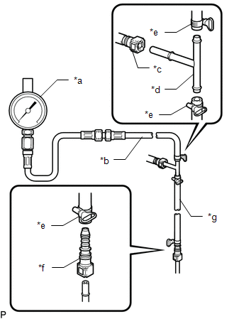
| (f) Install SST (EFI fuel pressure gauge and fuel pressure gauge adapter) as shown in the illustration. SST: 09268-45101 09268-41260 09268-41700 09268-41280 95336-08070 SST: 09268-00010 09268-00020 09268-00030 |
|
(g) Wipe up any spilled fuel.
(h) Connect the cable to the negative (-) auxiliary battery terminal.
(i) Perform initialization after reconnecting auxiliary battery terminal.
Click here
HINT:
When disconnecting and reconnecting the auxiliary battery, there is an automatic learning function that completes learning when the respective system is used.
Click here
(j) Connect the Techstream to the DLC3.
(k) Enter the following menus: Powertrain / Engine and ECT / Active Test / Control the Fuel Pump / Speed.
Powertrain > Engine and ECT > Active Test| Tester Display |
|---|
| Control the Fuel Pump / Speed |
(l) Measure the fuel pressure.
Standard fuel pressure:
304 to 343 kPa (3.1 to 3.5 kgf/cm2, 44 to 50 psi)
- If the fuel pressure is higher than the specification, replace the fuel pressure regulator assembly.
- If the fuel pressure is less than the standard, check the fuel hoses and connections, fuel pump, fuel filter assembly and fuel pressure regulator assembly.
(m) Disconnect the Techstream from the DLC3.
(n) Put the engine in inspection mode (maintenance mode).
Click here
(o) Start the engine.
(p) Measure the fuel pressure at idle.
Standard fuel pressure:
304 to 343 kPa (3.1 to 3.5 kgf/cm2, 44 to 50 psi)
(q) Stop the engine.
(r) Check that the fuel pressure remains as specified for 5 minutes after the engine stops.
Standard fuel pressure:
147 kPa (1.5 kgf/cm2, 21 psi) or more
If the fuel pressure is not as specified, check the fuel pump, fuel pressure regulator assembly and/or fuel injector assemblies.
(s) After checking the fuel pressure, disconnect the cable from the negative (-) auxiliary battery terminal and carefully remove SST to prevent fuel from spraying.
(t) Install the fuel tube sub-assembly to the fuel pipe.
Click here
(u) Install the No. 1 fuel pipe clamp to the fuel tube sub-assembly.
(v) Inspect for fuel leaks (check fuel pump operation and inspect for fuel leak).
3. ACTIVE TEST (Control the Select Cylinder Fuel Cut)
(a) Connect the Techstream to the DLC3.
(b) Put the engine in inspection mode (maintenance mode).
Click here
(c) Turn the Techstream on.
(d) Start the engine, then enter the following menus: Active Test / Control the Select Cylinder Fuel Cut. Select a cylinder from #1 to #4.
Powertrain > Engine and ECT > Active Test| Tester Display |
|---|
| Control the Select Cylinder Fuel Cut |
HINT:
Perform this procedure with the vehicle stopped and the engine idling.
(e) After stopping injection of the cylinder for which the Active Test was performed, check the idling state.
Standard:
The idling speed varies.
HINT:
Perform a test for each cylinder. It is not possible to test multiple cylinders at once.
READ NEXT:
 Components
COMPONENTS ILLUSTRATION *1 FRONT FLOOR COVER CENTER LH *2 FUEL TANK VENT HOSE SUB-ASSEMBLY *3 NO. 1 FLOOR UNDER COVER *4 NO. 1 FUEL TANK BAND *5 NO. 2 FUEL TANK BAND - -
Installation
INSTALLATION PROCEDURE 1. INSTALL NO. 4 FUEL TUBE CLAMP (a) Install the 5 No. 4 fuel tube clamps to the fuel tank assembly as shown in the illustration. 2. INSTALL FUEL TANK MAIN TUBE S
SEE MORE:
Fail-safe Chart
FAIL-SAFE CHART ASC System (a) The stereo component equalizer assembly stores DTCs and freeze frame data and stops sound output if it detects any of the following abnormalities. Item Abnormality Detection Condition Fail-safe Control DTC Output Return Condition CAN communication malfun
Inspection
INSPECTION PROCEDURE 1. INSPECT HEATER ACCESSORY ASSEMBLY *a Component without harness connected (Heater Accessory Assembly (Heater Water Pump)) (a) Check the motor operation. (1) Apply the positive (+) lead of the auxiliary battery to terminal 2 and the negative (-) lead to terminal 1. OK:
