Lexus NX: Installation
INSTALLATION
PROCEDURE
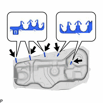
1. INSTALL NO. 4 FUEL TUBE CLAMP
| (a) Install the 5 No. 4 fuel tube clamps to the fuel tank assembly as shown in the illustration. |
|
2. INSTALL FUEL TANK MAIN TUBE SUB-ASSEMBLY
(a) Connect the 5 clamps and install the fuel tank main tube sub-assembly to the 5 No. 4 fuel tube clamps.
3. INSTALL FUEL SENDER GAUGE ASSEMBLY
Click here .gif)
4. INSTALL FUEL SUCTION TUBE ASSEMBLY
Click here
5. INSTALL FUEL TANK VENT TUBE SET PLATE
Click here
6. CONNECT FUEL TANK MAIN TUBE SUB-ASSEMBLY
Click here
7. INSTALL FUEL TANK ASSEMBLY
(a) Set the fuel tank assembly on an engine lifter with attachments.
(b) Raise the engine lifter.
NOTICE:
Be careful not to cut the wiring.
(c) Install the wire harness clamp to the 2 No. 4 fuel tube clamps.
(d) Connect the fuel pump connector and fuel sender gauge assembly connector.
(e) Connect the fuel tank breather tube sub-assembly to the fuel tank assembly.
Click here
(f) Install the No. 2 fuel tank band with the 2 bolts.
Torque:
45 N·m {459 kgf·cm, 33 ft·lbf}
(g) Install the No. 1 fuel tank band with the 2 bolts.
Torque:
45 N·m {459 kgf·cm, 33 ft·lbf}
(h) Connect the 4 wire harness clamps to the 3 No. 4 fuel tube clamps and the bracket on the vehicle side.
8. CONNECT FUEL TANK VENT HOSE SUB-ASSEMBLY
(a) Connect the fuel tank vent hose sub-assembly and clamp to the No. 2 fuel tank band.
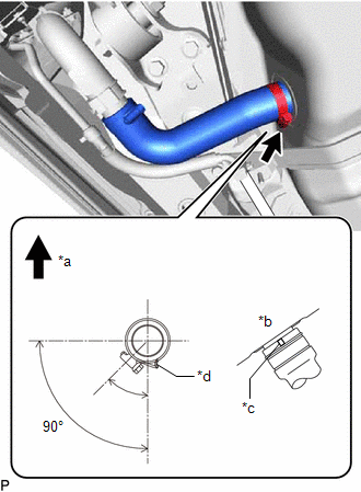
9. CONNECT FUEL TANK TO FILLER PIPE HOSE
| (a) Connect the fuel tank to filler pipe hose to the fuel tank assembly, then tighten the hose clamp. HINT: Make sure that the fuel tank to filler pipe hose and hose clamp are oriented as shown in the illustration. |
|
10. INSTALL FUEL HOSE PROTECTOR
(a) Attach the claw, then install the fuel hose protector to the fuel tank assembly and fuel tank to filler pipe hose.
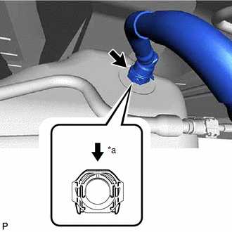
11. CONNECT FUEL TANK TO CANISTER TUBE SUB-ASSEMBLY
| (a) Connect the fuel tank to canister tube sub-assembly. (1) Push the hose into the port and push the retainer to lock it. NOTICE:
|
|
12. CONNECT FUEL TANK MAIN TUBE SUB-ASSEMBLY
(a) Connect the fuel tank main tube sub-assembly to the fuel pipe.
Click here
13. INSTALL NO. 1 FLOOR UNDER COVER
(a) Install the No. 1 floor under cover with the 2 nuts and attach the clip.
14. INSTALL FRONT FLOOR COVER CENTER LH
(a) Install the front floor cover center LH with the bolt, 2 nuts and 6 clips.
(b) Tighten the nut.
15. ADD FUEL
16. CONNECT CABLE TO NEGATIVE AUXILIARY BATTERY TERMINAL
17. INITIALIZATION AFTER RECONNECTING AUXILIARY BATTERY TERMINAL
Click here
HINT:
When disconnecting and reconnecting the auxiliary battery, there is an automatic learning function that completes learning when the respective system is used.
Click here
18. INSPECT FOR FUEL LEAK
Click here
READ NEXT:
 Accelerator Pedal Sensor
ComponentsCOMPONENTS ILLUSTRATION *1 ACCELERATOR PEDAL SENSOR ASSEMBLY *2 ACCELERATOR PEDAL SENSOR CONNECTOR N*m (kgf*cm, ft.*lbf): Specified torque - - On-vehicle Inspection
SEE MORE:
Deceleration Sensor (C1245)
DESCRIPTION The parking brake ECU assembly receives vehicle tilt information from the deceleration sensor (airbag ECU assembly) via CAN communication. DTC No. Detection Item DTC Detection Condition Trouble Area Memory Note C1245 Deceleration Sensor One of the following condition
Problem Symptoms Table
PROBLEM SYMPTOMS TABLE NOTICE:
If the auxiliary battery voltage is low, the climate control seat system may not operate. When "High Power Consumption Partial Limit On AC/Heater Operation." is displayed on the multi-information display in the combination meter assembly, inspect the auxiliary batte
