Lexus NX: Components
COMPONENTS
ILLUSTRATION
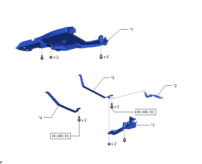
| *1 | FRONT FLOOR COVER CENTER LH | *2 | FUEL TANK VENT HOSE SUB-ASSEMBLY |
| *3 | NO. 1 FLOOR UNDER COVER | *4 | NO. 1 FUEL TANK BAND |
| *5 | NO. 2 FUEL TANK BAND | - | - |
.png) | N*m (kgf*cm, ft.*lbf): Specified torque | - | - |
ILLUSTRATION
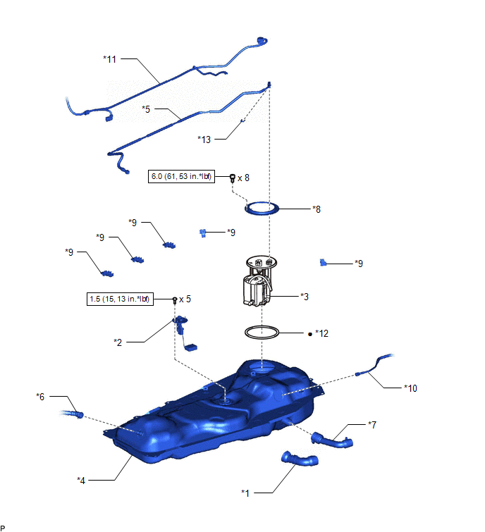
| *1 | FUEL HOSE PROTECTOR | *2 | FUEL SENDER GAUGE ASSEMBLY |
| *3 | FUEL SUCTION TUBE ASSEMBLY | *4 | FUEL TANK ASSEMBLY |
| *5 | FUEL TANK MAIN TUBE SUB-ASSEMBLY | *6 | FUEL TANK TO CANISTER TUBE SUB-ASSEMBLY |
| *7 | FUEL TANK TO FILLER PIPE HOSE | *8 | FUEL TANK VENT TUBE SET PLATE |
| *9 | NO. 4 FUEL TUBE CLAMP | *10 | FUEL TANK BREATHER TUBE SUB-ASSEMBLY |
| *11 | WIRE HARNESS | *12 | GASKET |
| *13 | TUBE JOINT CLIP | - | - |
| | N*m (kgf*cm, ft.*lbf): Specified torque | ● | Non-reusable part |
READ NEXT:
 Installation
INSTALLATION PROCEDURE 1. INSTALL NO. 4 FUEL TUBE CLAMP (a) Install the 5 No. 4 fuel tube clamps to the fuel tank assembly as shown in the illustration. 2. INSTALL FUEL TANK MAIN TUBE S
Accelerator Pedal Sensor
ComponentsCOMPONENTS ILLUSTRATION *1 ACCELERATOR PEDAL SENSOR ASSEMBLY *2 ACCELERATOR PEDAL SENSOR CONNECTOR N*m (kgf*cm, ft.*lbf): Specified torque - - On-vehicle Inspection
SEE MORE:
Removal
REMOVAL CAUTION / NOTICE / HINT NOTICE:
Do not replace the spiral cable with the battery connected and the power switch on (IG).
Do not rotate the spiral cable when the following conditions are met: 1) The steering wheel is removed, 2) the battery is connected, and 3) thepower switch on (IG).
Problem Symptoms Table
PROBLEM SYMPTOMS TABLE HINT:
Use the table below to help determine the cause of problem symptoms. If multiple suspected areas are listed, the potential causes of the symptoms are listed in order of probability in the "Suspected Area" column of the table. Check each symptom by checking the suspect
© 2016-2026 Copyright www.lexunx.com
