- Power switch off
- High mounted stop light off
- Luggage compartment room light off
- Window defogger off
Lexus NX: On-vehicle Inspection
Lexus NX Service Manual / Audio & Visual & Telematics / Audio / Video / Noise Filter / On-vehicle Inspection
ON-VEHICLE INSPECTION
PROCEDURE
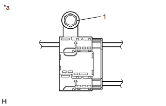
1. INSPECT RADIO SETTING CONDENSER
(a) With the radio setting condenser installed, check that there is no looseness or other abnormalities.
| (b) Measure the resistance of the radio setting condenser according to the value(s) in the table below. Standard Resistance:
|
|
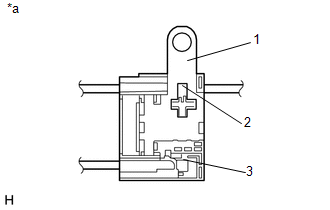
(c) Remove the bolt.
(d) Disengage the clamp and disconnect the radio setting condenser with wire harness from the vehicle body.
| (e) Measure the resistance and voltage of the radio setting condenser according to the value(s) in the table below. Standard Resistance:
Standard Voltage:
|
|
READ NEXT:
 Removal
REMOVAL PROCEDURE 1. REMOVE REAR SEAT ASSEMBLY (for Manual Seat) Click here 2. REMOVE REAR SEAT ASSEMBLY (for Power Seat) Click here 3. REMOVE TONNEAU COVER ASSEMBLY Click here 4. REMOVE DE
Installation
INSTALLATION PROCEDURE 1. INSTALL RADIO SETTING CONDENSER (a) Attach the claw to install a new terminal cover to the wire harness. NOTICE:
Make sure to hold the crimping side of the terminal w
SEE MORE:
Removal
REMOVAL PROCEDURE 1. REMOVE FRONT BUMPER ASSEMBLY (a) for Sport Package: Click here (b) except Sport Package: Click here 2. REMOVE MILLIMETER WAVE RADAR SENSOR ASSEMBLY NOTICE: Do not reuse the millimeter wave radar sensor assembly if it has been dropped or subjected to a severe impact. (a) Remo
Steering Angle Sensor Unusual Bank Angle Detected (C1440)
DESCRIPTION If the skid control ECU (brake booster with master cylinder assembly) determines that the vehicle is being driven at a steep bank angle, the skid control ECU (brake booster with master cylinder assembly) stores DTC C1440 while VSC operation is temporarily disabled. This is not a malfunct
© 2016-2026 Copyright www.lexunx.com
