Lexus NX: Removal
REMOVAL
PROCEDURE
1. REMOVE REAR SEAT ASSEMBLY (for Manual Seat)
Click here .gif)
2. REMOVE REAR SEAT ASSEMBLY (for Power Seat)
Click here
3. REMOVE TONNEAU COVER ASSEMBLY
Click here
4. REMOVE DECK BOARD ASSEMBLY
Click here
5. REMOVE NO. 2 DECK BOARD SUB-ASSEMBLY
Click here
6. REMOVE NO. 3 DECK BOARD SUB-ASSEMBLY
Click here
7. REMOVE REAR DECK FLOOR BOX
Click here
8. REMOVE SPARE TIRE
Click here
9. REMOVE DECK FLOOR BOX LH
Click here
10. REMOVE DECK FLOOR BOX RH
Click here
11. REMOVE NO. 1 TOOL BOX SUB-ASSEMBLY
Click here
12. REMOVE NO. 2 TOOL BOX SUB-ASSEMBLY
Click here
13. REMOVE REAR FLOOR FINISH PLATE
Click here
14. REMOVE REAR DOOR SCUFF PLATE LH
Click here
15. REMOVE REAR DOOR OPENING TRIM WEATHERSTRIP LH
Click here
16. REMOVE UPPER DECK TRIM SIDE BOARD LH
Click here
17. REMOVE ROPE HOOK ASSEMBLY
Click here
18. REMOVE LUGGAGE HOLD BELT STRIKER ASSEMBLY
Click here
19. REMOVE NO. 1 LUGGAGE COMPARTMENT TRIM HOOK
Click here
20. REMOVE DECK TRIM SIDE PANEL ASSEMBLY LH
Click here
21. REMOVE INNER ROOF SIDE GARNISH ASSEMBLY LH
Click here
22. REMOVE RADIO SETTING CONDENSER
NOTICE:
When a terminal cover is removed, the radio setting condenser must be replaced because the terminal covers and condenser are supplied as a set.
| (a) Remove the bolt. |
|
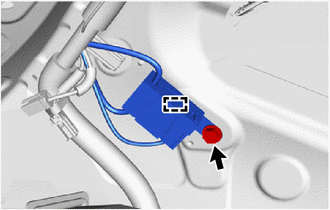
(b) Detach the clamp and disconnect the radio setting condenser with wire harness from the vehicle body.
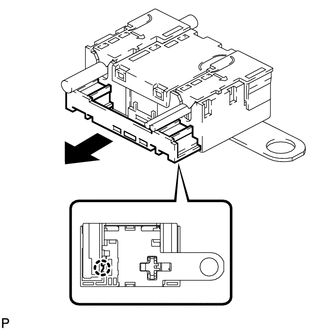
| (c) Detach the claw and pull out the cover as shown in the illustration. |
|
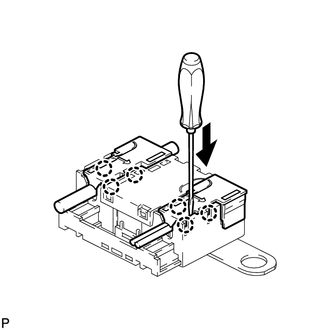
| (d) Using a screwdriver, detach the 6 claws and remove the 2 terminal covers with wire harness from the condenser. |
|
| (e) Using a screwdriver, bend back and break off the claw as shown in the illustration. |
|
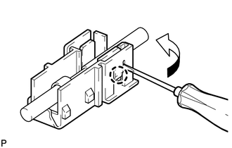
(f) Remove the terminal cover from the wire harness.
NOTICE:
- Make sure to hold the crimping side of the terminal when disconnecting the wire harness from the terminal cover.
- Make sure not to bend the exposed wire when disconnecting the wire harness from the terminal cover.
- Check for deformation of the terminal after the wire harness has been removed from the terminal cover.
READ NEXT:
 Installation
INSTALLATION PROCEDURE 1. INSTALL RADIO SETTING CONDENSER (a) Attach the claw to install a new terminal cover to the wire harness. NOTICE:
Make sure to hold the crimping side of the terminal w
Components
COMPONENTS ILLUSTRATION *1 DECK BOARD ASSEMBLY *2 NO. 2 DECK BOARD SUB-ASSEMBLY *3 NO. 3 DECK BOARD SUB-ASSEMBLY *4 TONNEAU COVER ASSEMBLY ILLUSTRATION *1 DECK FLOOR BOX L
SEE MORE:
Problem Symptoms Table
PROBLEM SYMPTOMS TABLE HINT:
Use the table below to help determine the cause of problem symptoms. If multiple suspected areas are listed, the potential causes of the symptoms are listed in order of probability in the "Suspected Area" column of the table. Check each symptom by checking the suspect
Removal
REMOVAL PROCEDURE 1. REMOVE NO. 3 DECK BOARD SUB-ASSEMBLY Click here 2. REMOVE REAR DECK FLOOR BOX Click here 3. REMOVE DECK FLOOR BOX LH Click here 4. PRECAUTION CAUTION: Be sure to read Precaution thoroughly before servicing. Click here NOTICE:
After the power switch is turned off, ther
