Lexus NX: One or more Power Seat Motors do not Operate
DESCRIPTION
Signals are input into the front power seat switch LH. The built-in ECU manages the signals received from the front power seat switch LH, and operates each motor. If the front power seat switch LH receives more than 2 motor operation signals, the motor is stopped. Manual operation is restarted after the front power seat switch LH receives 1 signal only.
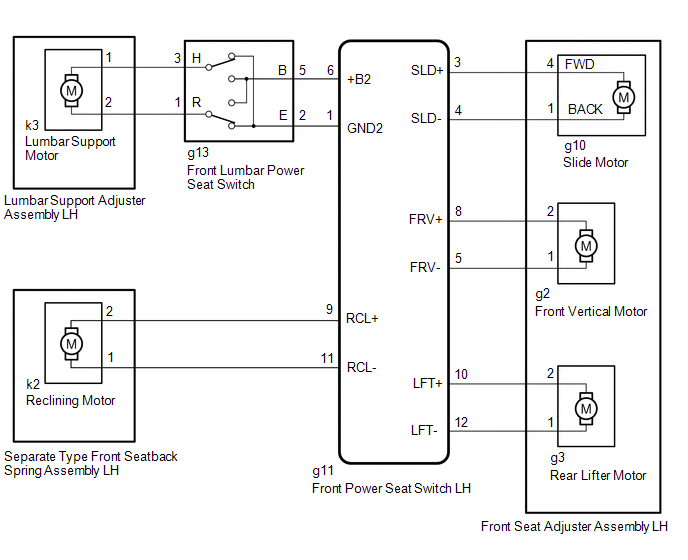
WIRING DIAGRAM
CAUTION / NOTICE / HINT
HINT:
If DTC B2650 or B2658 is output, first perform troubleshooting these DTCs.
PROCEDURE
| 1. | CHECK FRONT POWER SEAT OPERATION |
(a) Check that each function of the power seat operates normally by using the front power seat switch LH.
Click here .gif)
| Result | Proceed to |
|---|---|
| All power seat functions do not operate | A |
| Only slide function does not operate | B |
| Only front vertical function does not operate | C |
| Only rear lifter function does not operate | D |
| Only reclining function does not operate | E |
| Only lumbar support adjustment function does not operate | F |
| A | .gif) | GO TO OTHER DIAGNOSIS PROCEDURE (Front Power Seat does not Operate with Front Power Seat Switch) |
| C | | GO TO STEP 6 |
| D | | GO TO STEP 10 |
| E | | GO TO STEP 14 |
| F | | GO TO STEP 18 |
|
.gif)
| 2. | READ VALUE USING TECHSTREAM (SLIDE REAR, SLIDE FRONT) |
(a) Connect the Techstream to the DLC3.
(b) Turn the power switch on (IG).
(c) Turn the Techstream on.
(d) Enter the following menus: Body Electrical / Driver Seat / Data List.
(e) Read the Data List according to the display on the Techstream.
Body Electrical > Driver Seat > Data List| Tester Display | Measurement Item | Range | Normal Condition | Diagnostic Note |
|---|---|---|---|---|
| Slide Rear | Slide switch signal (Rearward) | ON or OFF | ON: Slide switch (Rearward) on OFF: Slide switch (Rearward) off | - |
| Slide Front | Slide switch signal (Forward) | ON or OFF | ON: Slide switch (Forward) on OFF: Slide switch (Forward) off | - |
| Tester Display |
|---|
| Slide Rear |
| Slide Front |
OK:
The Techstream display changes correctly in response to the switch operation.
| NG | | REPLACE FRONT POWER SEAT SWITCH LH |
|
| 3. | PERFORM ACTIVE TEST USING TECHSTREAM (SEAT SLIDE OPERATION) |
(a) Enter the following menus: Body Electrical / Driver Seat / Active Test.
(b) Perform the Active Test according to the display on the Techstream.
Body Electrical > Driver Seat > Active Test| Tester Display | Measurement Item | Control Range | Diagnostic Note |
|---|---|---|---|
| Seat Slide Operation | Seat slide operation | OFF/Rear/Front | - |
| Tester Display |
|---|
| Seat Slide Operation |
OK:
Front seat assembly is moved normally using the Techstream operation.
| OK | | REPLACE FRONT POWER SEAT SWITCH LH |
|
| 4. | INSPECT FRONT SEAT ADJUSTER ASSEMBLY LH (SLIDE MOTOR) |
(a) Remove the front seat adjuster assembly LH.
Click here
(b) Inspect the front seat adjuster assembly LH.
Click here
| NG | | REPLACE FRONT SEAT ADJUSTER ASSEMBLY LH |
|
| 5. | CHECK HARNESS AND CONNECTOR (FRONT POWER SEAT SWITCH LH - FRONT SEAT ADJUSTER ASSEMBLY LH [SLIDE MOTOR]) |
(a) Disconnect the g11 front power seat switch LH connector.
(b) Disconnect the g10 front seat adjuster assembly LH connector.
(c) Measure the resistance according to the value(s) in the table below.
Standard Resistance:
| Tester Connection | Condition | Specified Condition |
|---|---|---|
| g11-3 (SLD+) - g10-4 (FWD) | Always | Below 1 Ω |
| g11-3 (SLD+) or g10-4 (FWD) - Body ground | Always | 10 kΩ or higher |
| g11-4 (SLD-) - g10-1 (BACK) | Always | Below 1 Ω |
| g11-4 (SLD-) or g10-1 (BACK) - Body ground | Always | 10 kΩ or higher |
| OK | | REPLACE FRONT POWER SEAT SWITCH LH |
| NG | | REPAIR OR REPLACE HARNESS OR CONNECTOR |
| 6. | READ VALUE USING TECHSTREAM (FRONT VERTICAL DOWN, FRONT VERTICAL UP) |
(a) Connect the Techstream to the DLC3.
(b) Turn the power switch on (IG).
(c) Turn the Techstream on.
(d) Enter the following menus: Body Electrical / Driver Seat / Data List.
(e) Read the Data List according to the display on the Techstream.
Body Electrical > Driver Seat > Data List| Tester Display | Measurement Item | Range | Normal Condition | Diagnostic Note |
|---|---|---|---|---|
| Front Vertical Down | Front vertical switch signal (Downward) | ON or OFF | ON: Front vertical switch (Downward) on OFF: Front vertical switch (Downward) off | - |
| Front Vertical Up | Front vertical switch signal (Upward) | ON or OFF | ON: Front vertical switch (Upward) on OFF: Front vertical switch (Upward) off | - |
| Tester Display |
|---|
| Front Vertical Down |
| Front Vertical Up |
OK:
The Techstream display changes correctly in response to the switch operation.
| NG | | REPLACE FRONT POWER SEAT SWITCH LH |
|
| 7. | PERFORM ACTIVE TEST USING TECHSTREAM (FRONT VERTICAL OPERATION) |
(a) Enter the following menus: Body Electrical / Driver Seat / Active Test.
(b) Perform the Active Test according to the display on the Techstream.
Body Electrical > Driver Seat > Active Test| Tester Display | Measurement Item | Control Range | Diagnostic Note |
|---|---|---|---|
| Front Vertical Operation | Seat front vertical operation | OFF/Down/Up | - |
| Tester Display |
|---|
| Front Vertical Operation |
OK:
Front seat assembly is moved normally using the Techstream operation.
| OK | | REPLACE FRONT POWER SEAT SWITCH LH |
|
| 8. | INSPECT FRONT SEAT ADJUSTER ASSEMBLY LH (FRONT VERTICAL MOTOR) |
(a) Remove the front seat adjuster assembly LH.
Click here
(b) Inspect the front seat adjuster assembly LH.
Click here
| NG | | REPLACE FRONT SEAT ADJUSTER ASSEMBLY LH |
|
| 9. | CHECK HARNESS AND CONNECTOR (FRONT POWER SEAT SWITCH LH - FRONT SEAT ADJUSTER ASSEMBLY LH [FRONT VERTICAL MOTOR]) |
(a) Disconnect the g11 front power seat switch LH connector.
(b) Disconnect the g2 front seat adjuster assembly LH connector.
(c) Measure the resistance according to the value(s) in the table below.
Standard Resistance:
| Tester Connection | Condition | Specified Condition |
|---|---|---|
| g11-5 (FRV-) - g2-1 | Always | Below 1 Ω |
| g11-5 (FRV-) or g2-1 - Body ground | Always | 10 kΩ or higher |
| g11-8 (FRV+) - g2-2 | Always | Below 1 Ω |
| g11-8 (FRV+) or g2-2 - Body ground | Always | 10 kΩ or higher |
| OK | | REPLACE FRONT POWER SEAT SWITCH LH |
| NG | | REPAIR OR REPLACE HARNESS OR CONNECTOR |
| 10. | READ VALUE USING TECHSTREAM (LIFTER SWITCH DOWN, LIFTER SWITCH UP) |
(a) Connect the Techstream to the DLC3.
(b) Turn the power switch on (IG).
(c) Turn the Techstream on.
(d) Enter the following menus: Body Electrical / Driver Seat / Data List.
(e) Read the Data List according to the display on the Techstream.
Body Electrical > Driver Seat > Data List| Tester Display | Measurement Item | Range | Normal Condition | Diagnostic Note |
|---|---|---|---|---|
| Lifter Switch Down | Lifter switch signal (Downward) | ON or OFF | ON: Lifter switch (Downward) on OFF: Lifter switch (Downward) off | - |
| Lifter Switch Up | Lifter switch signal (Upward) | ON or OFF | ON: Lifter switch (Upward) on OFF: Lifter switch (Upward) off | - |
| Tester Display |
|---|
| Lifter Switch Down |
| Lifter Switch Up |
OK:
The Techstream display changes correctly in response to the switch operation.
| NG | | REPLACE FRONT POWER SEAT SWITCH LH |
|
| 11. | PERFORM ACTIVE TEST USING TECHSTREAM (LIFTER OPERATION) |
(a) Enter the following menus: Body Electrical / Driver Seat / Active Test.
(b) Perform the Active Test according to the display on the Techstream.
Body Electrical > Driver Seat > Active Test| Tester Display | Measurement Item | Control Range | Diagnostic Note |
|---|---|---|---|
| Lifter Operation | Seat lifter operation | OFF/Down/Up | - |
| Tester Display |
|---|
| Lifter Operation |
OK:
Front seat assembly is moved normally using the Techstream operation.
| OK | | REPLACE FRONT POWER SEAT SWITCH LH |
|
| 12. | INSPECT FRONT SEAT ADJUSTER ASSEMBLY LH (REAR LIFTER MOTOR) |
(a) Remove the front seat adjuster assembly LH.
Click here
(b) Inspect the front seat adjuster assembly LH.
Click here
| NG | | REPLACE FRONT SEAT ADJUSTER ASSEMBLY LH |
|
| 13. | CHECK HARNESS AND CONNECTOR (FRONT POWER SEAT SWITCH LH - FRONT SEAT ADJUSTER ASSEMBLY LH [REAR LIFTER MOTOR]) |
(a) Disconnect the g11 front power seat switch LH connector.
(b) Disconnect the g3 front seat adjuster assembly LH connector.
(c) Measure the resistance according to the value(s) in the table below.
Standard Resistance:
| Tester Connection | Condition | Specified Condition |
|---|---|---|
| g11-10 (LFT+) - g3-2 | Always | Below 1 Ω |
| g11-10 (LFT+) or g3-2 - Body ground | Always | 10 kΩ or higher |
| g11-12 (LFT-) - g3-1 | Always | Below 1 Ω |
| g11-12 (LFT-) or g3-1 - Body ground | Always | 10 kΩ or higher |
| OK | | REPLACE FRONT POWER SEAT SWITCH LH |
| NG | | REPAIR OR REPLACE HARNESS OR CONNECTOR |
| 14. | READ VALUE USING TECHSTREAM (RECLINING REAR, RECLINING FRONT) |
(a) Connect the Techstream to the DLC3.
(b) Turn the power switch on (IG).
(c) Turn the Techstream on.
(d) Enter the following menus: Body Electrical / Driver Seat / Data List.
(e) Read the Data List according to the display on the Techstream.
Body Electrical > Driver Seat > Data List| Tester Display | Measurement Item | Range | Normal Condition | Diagnostic Note |
|---|---|---|---|---|
| Reclining Rear | Reclining switch signal (Rearward) | ON or OFF | ON: Reclining switch (Rearward) on OFF: Reclining switch (Rearward) off | - |
| Reclining Front | Reclining switch signal (Forward) | ON or OFF | ON: Reclining switch (Forward) on OFF: Reclining switch (Forward) off | - |
| Tester Display |
|---|
| Reclining Rear |
| Reclining Front |
OK:
The Techstream display changes correctly in response to the switch operation.
| NG | | REPLACE FRONT POWER SEAT SWITCH LH |
|
| 15. | PERFORM ACTIVE TEST USING TECHSTREAM (SEAT RECLINING) |
(a) Enter the following menus: Body Electrical / Driver Seat / Active Test.
(b) Perform the Active Test according to the display on the Techstream.
Body Electrical > Driver Seat > Active Test| Tester Display | Measurement Item | Control Range | Diagnostic Note |
|---|---|---|---|
| Seat Reclining | Seat reclining operation | OFF/Rear/Front | - |
| Tester Display |
|---|
| Seat Reclining |
OK:
Front seat assembly is moved normally using the Techstream operation.
| OK | | REPLACE FRONT POWER SEAT SWITCH LH |
|
| 16. | INSPECT SEPARATE TYPE FRONT SEATBACK SPRING ASSEMBLY LH (RECLINING MOTOR) |
(a) Remove the separate type front seatback spring assembly LH.
Click here
(b) Inspect the separate type front seatback spring assembly LH.
Click here
| NG | | REPLACE SEPARATE TYPE FRONT SEATBACK SPRING ASSEMBLY LH |
|
| 17. | CHECK HARNESS AND CONNECTOR (FRONT POWER SEAT SWITCH LH - SEPARATE TYPE FRONT SEATBACK SPRING ASSEMBLY LH [RECLINING MOTOR]) |
(a) Disconnect the g11 front power seat switch LH connector.
(b) Disconnect the k2 separate type front seatback spring assembly LH connector.
(c) Measure the resistance according to the value(s) in the table below.
Standard Resistance:
| Tester Connection | Condition | Specified Condition |
|---|---|---|
| g11-9 (RCL+) - k2-2 | Always | Below 1 Ω |
| g11-9 (RCL+) or k2-2 - Body ground | Always | 10 kΩ or higher |
| g11-11 (RCL-) - k2-1 | Always | Below 1 Ω |
| g11-11 (RCL-) or k2-1 - Body ground | Always | 10 kΩ or higher |
| OK | | REPLACE FRONT POWER SEAT SWITCH LH |
| NG | | REPAIR OR REPLACE HARNESS OR CONNECTOR |
| 18. | INSPECT FRONT LUMBAR POWER SEAT SWITCH |
(a) Remove the front lumbar power seat switch.
Click here
(b) Inspect the front lumbar power seat switch.
Click here
| NG | | REPLACE FRONT LUMBAR POWER SEAT SWITCH |
|
| 19. | INSPECT LUMBAR SUPPORT ADJUSTER ASSEMBLY LH (LUMBAR SUPPORT MOTOR) |
(a) Remove the lumbar support adjuster assembly LH.
Click here
(b) Inspect the lumbar support adjuster assembly LH.
Click here
| NG | | REPLACE LUMBAR SUPPORT ADJUSTER ASSEMBLY LH |
|
| 20. | CHECK HARNESS AND CONNECTOR (FRONT POWER SEAT SWITCH LH - FRONT LUMBAR POWER SEAT SWITCH) |
(a) Disconnect the g11 front power seat switch LH connector.
(b) Disconnect the g13 front lumbar power seat switch connector.
(c) Measure the resistance according to the value(s) in the table below.
Standard Resistance:
| Tester Connection | Condition | Specified Condition |
|---|---|---|
| g11-6 (+B2) - g13-5 (B) | Always | Below 1 Ω |
| g11-6 (+B2) or g13-5 (B) - Body ground | Always | 10 kΩ or higher |
| g11-1 (GND2) - g13-2 (E) | Always | Below 1 Ω |
| g11-1 (GND2) or g13-2 (E) - Body ground | Always | 10 kΩ or higher |
| NG | | REPAIR OR REPLACE HARNESS OR CONNECTOR |
|
| 21. | CHECK HARNESS AND CONNECTOR (FRONT LUMBAR POWER SEAT SWITCH - LUMBAR SUPPORT ADJUSTER ASSEMBLY LH [LUMBAR SUPPORT MOTOR]) |
(a) Disconnect the g13 front lumbar power seat switch connector.
(b) Disconnect the k3 lumbar support adjuster assembly LH connector.
(c) Measure the resistance according to the value(s) in the table below.
Standard Resistance:
| Tester Connection | Condition | Specified Condition |
|---|---|---|
| g13-1 (R) - k3-2 | Always | Below 1 Ω |
| g13-1 (R) or k3-2 - Body ground | Always | 10 kΩ or higher |
| g13-3 (H) - k3-1 | Always | Below 1 Ω |
| g13-3 (H) or k3-1 - Body ground | Always | 10 kΩ or higher |
| OK | | REPLACE FRONT POWER SEAT SWITCH LH |
| NG | | REPAIR OR REPLACE HARNESS OR CONNECTOR |
READ NEXT:
 Power Seat Position is not Memorized
DESCRIPTION The main body ECU (multiplex network body ECU) receives seat memory switch signals from the outer mirror control ECU assembly (for Driver Side) via CAN communication. If the seat memory SE
Power Seat does not Return to Memorized Position
DESCRIPTION When either the M1, M2 or M3 switch is pressed, the outer mirror control ECU assembly (for Driver Side) sends a switch signal to the main body ECU (multiplex network body ECU) via CAN comm
Wireless Transmitter Memory Function does not Operate
DESCRIPTION With the power switch on (IG) and the driver door closed, pressing the manual lock or unlock switch on the multiplex network master switch assembly while holding a seat memory switch (M1,
SEE MORE:
Components
COMPONENTS ILLUSTRATION *1 COWL SIDE TRIM BOARD LH *2 DOOR SCUFF PLATE ASSEMBLY LH *3 FRONT FLOOR CARPET ASSEMBLY *4 NO. 4 DASH PANEL INSULATOR PAD (FRONT FLOOR FOOTREST)
Operation Check
OPERATION CHECK CHECK BASIC OPERATION NOTICE:
This check is possible only when the "Power Back Door Function" customization setting using the multi-information display in the combination meter assembly is set to ON (initial setting is ON).
Click here
Before performing an operation check, chec
