Lexus NX: Open in Outer Mirror Indicator(Master) (C1AB4)
DESCRIPTION
This DTC is stored when the blind spot monitor sensor LH detects an open in the outer rear view mirror indicator LH.
| DTC No. | Detection Item | DTC Detection Condition | Trouble Area | Note |
|---|---|---|---|---|
| C1AB4 | Open in Outer Mirror Indicator(Master) | Both of the following conditions are met:
|
| - |
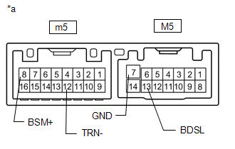
WIRING DIAGRAM
.png)
CAUTION / NOTICE / HINT
NOTICE:
When checking for DTCs, make sure that the blind spot monitor main switch (combination switch assembly) is on.
PROCEDURE
| 1. | CHECK DTC |
(a) Clear the DTCs.
Click here .gif)
(b) Recheck for DTCs and check if the same DTC is output again.
Body Electrical > Blind Spot Monitor Master > Trouble CodesOK:
DTC C1AB4 is not output.
| OK | .gif) | USE SIMULATION METHOD TO CHECK |
|
.gif)
| 2. | CHECK HARNESS AND CONNECTOR (BLIND SPOT MONITOR SENSOR LH - OUTER MIRROR CONTROL ECU ASSEMBLY LH AND BODY GROUND) |
(a) Disconnect the V1 blind spot monitor sensor LH connector.
(b) Disconnect the M5 outer mirror control ECU assembly LH connector.
(c) Measure the resistance according to the value(s) in the table below.
Standard Resistance:
| Tester Connection | Condition | Specified Condition |
|---|---|---|
| V1-4 (OMIL) - M5-13 (BDSL) | Always | Below 1 Ω |
| M5-7 (GND) - Body ground | Always | Below 1 Ω |
| NG | | REPAIR OR REPLACE HARNESS OR CONNECTOR |
|
| 3. | INSPECT OUTER MIRROR CONTROL ECU ASSEMBLY LH |
| (a) Remove the outer mirror control ECU assembly LH. Click here |
|
(b) Measure the resistance according to the value(s) in the table below.
Standard Resistance:
| Tester Connection | Condition | Specified Condition |
|---|---|---|
| M5-13 (BDSL) - m5-8 (BSM+) | Always | Below 1 Ω |
| M5-7 (GND) - m5-12 (TRN-) | Always | Below 1 Ω |
| NG | | REPLACE OUTER MIRROR CONTROL ECU ASSEMBLY LH |
|
| 4. | CHECK OUTER REAR VIEW MIRROR ASSEMBLY LH |
(a) Disconnect the m5 outer mirror control ECU assembly LH connector.
(b) Disconnect the IND1 outer mirror LH connector.
(c) Measure the resistance according to the value(s) in the table below.
Standard Resistance:
| Tester Connection | Condition | Specified Condition |
|---|---|---|
| m5-8 (BSM+) - IND1-2 (+) | Always | Below 1 Ω |
| m5-12 (TRN-) - IND1-1 (-) | Always | Below 1 Ω |
| NG | | REPLACE OUTER MIRROR RETRACTOR LH |
|
| 5. | INSPECT OUTER MIRROR LH |
(a) Replace the outer mirror LH.
Click here
(b) Inspect the outer rear view mirror indicator LH on the outer mirror LH.
Click here
| OK | | REPLACE BLIND SPOT MONITOR SENSOR LH |
| NG | | REPLACE OUTER MIRROR LH (OUTER REAR VIEW MIRROR INDICATOR LH) |
READ NEXT:
 Open in Outer Mirror Indicator(Slave) (C1AB5)
DESCRIPTION This DTC is stored when the blind spot monitor sensor RH detects an open in the outer rear view mirror indicator RH. DTC No. Detection Item DTC Detection Condition Trouble Area
Blind Spot Monitor Master Module (C1AB6)
DESCRIPTION This DTC is stored when the blind spot monitor sensor LH detects an internal malfunction. DTC No. Detection Item DTC Detection Condition Trouble Area Note C1AB6 Blind Spot
Blind Spot Monitor Slave Module (C1AB7)
DESCRIPTION This DTC is stored when the blind spot monitor sensor RH detects an internal malfunction. DTC No. Detection Item DTC Detection Condition Trouble Area Note C1AB7 Blind Spot
SEE MORE:
Problem Symptoms Table
PROBLEM SYMPTOMS TABLE NOTICE:
After replacing the radio receiver assembly of vehicles subscribed to pay-type satellite radio broadcasts, registration of the XM radio ID is necessary (w/ SXM System).
If the DCM (telematics transceiver) has been replaced, perform the DCM Activation procedure usi
How To Proceed With Troubleshooting
CAUTION / NOTICE / HINT HINT: Use these procedures to troubleshoot the adaptive variable suspension system. *: Use the Techstream. PROCEDURE 1. VEHICLE BROUGHT TO WORKSHOP
NEXT 2. PROBLEM SYMPTOM CONFIRMATION
NEXT 3. INSPECT AUXILIARY BATTERY
