Lexus NX: Open in Turn Signal Circuit (B1507,B1508)
DESCRIPTION
These DTCs are stored when the combination meter assembly detects an open in a turn signal light circuit, a short in a turn signal light circuit, or a short in the hazard warning light circuit.
| DTC No. | Detection Item | DTC Detection Condition | Trouble Area |
|---|---|---|---|
| B1507 | Open in Turn Signal Circuit | Both conditions are met:
|
|
| B1508 | Short in Turn Signal / Hazard Flasher Circuit | Both conditions are met:
|
|
-
*1: w/ Memory
*2: for Triple Beam Headlight
WIRING DIAGRAM
CAUTION / NOTICE / HINT
NOTICE:
- When replacing the combination meter assembly, make sure to replace it with a new one.
- Inspect the bulbs for circuits related to this system before performing the following inspection procedure.
PROCEDURE
| 1. | CHECK FOR DTC |
(a) Clear the DTCs.
Click here .gif)
(b) Recheck for DTCs and check that no DTCs are output.
Click here
OK:
B1507 and B1508 are not output.
| OK | .gif) | USE SIMULATION METHOD TO CHECK |
|
.gif)
| 2. | INSPECT LIGHTS |
(a) Inspect the illumination of each turn signal light.
| Result | Proceed to |
|---|---|
| Front LH side turn signal light does not illuminate. | A |
| Front RH side turn signal light does not illuminate. | B |
| Rear LH side turn signal light does not illuminate. | C |
| Rear RH side turn signal light does not illuminate. | D |
| B | | GO TO STEP 9 |
| C | | GO TO STEP 15 |
| D | | GO TO STEP 17 |
|
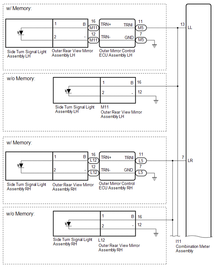
| 3. | CHECK HARNESS AND CONNECTOR (FRONT LH SIDE CIRCUIT) |
- *: for Triple Beam Headlight
(a) Disconnect the I11 combination meter assembly connector.
(b) Disconnect the M11 outer rear view mirror assembly LH connector.
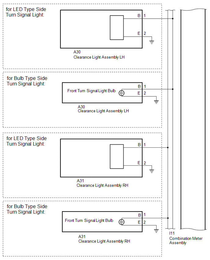
(c) Disconnect the A30 clearance light assembly LH connector.
(d) Disconnect the A19 headlight light control ECU sub-assembly LH connector.*
(e) Measure the resistance according to the value(s) in the table below.
Standard Resistance:
| Tester Connection | Condition | Specified Condition |
|---|---|---|
| I11-13 (LL) - M11-16 (B) | Always | Below 1 Ω |
| I11-13 (LL) - A30-1 (B) | Always | Below 1 Ω |
| I11-13 (LL) - A19-11 (TNS)* | Always | Below 1 Ω |
| M11-12 (-) - Body ground | Always | Below 1 Ω |
| A30-2 (E) - Body ground | Always | Below 1 Ω |
| I11-13 (LL) or M11-16 (B) - Body ground | Always | 10 kΩ or higher |
| I11-13 (LL) or A30-1 (B) - Body ground | Always | 10 kΩ or higher |
| I11-13 (LL) or A19-11 (TNS) - Body ground* | Always | 10 kΩ or higher |
| Result | Proceed to |
|---|---|
| OK | A |
| NG (w/ Memory) | B |
| NG (w/o Memory) | C |
| B | | GO TO STEP 7 |
| C | | REPAIR OR REPLACE HARNESS OR CONNECTOR |
|
| 4. | INSPECT OUTER REAR VIEW MIRROR ASSEMBLY LH |
(a) Remove the outer rear view mirror assembly LH.
Click here
(b) Inspect the outer rear view mirror assembly LH.
Click here
| NG | | GO TO STEP 8 |
|
| 5. | INSPECT CLEARANCE LIGHT ASSEMBLY LH |
(a) Remove the clearance light assembly LH.
for LED Type Turn Signal Light: Click here
for Bulb Type Turn Signal Light: Click here
(b) Inspect the clearance light assembly LH.
for LED Type Turn Signal Light: Click here
for Bulb Type Turn Signal Light: Click here
| Result | Proceed to |
|---|---|
| OK (for Triple Beam Headlight) | A |
| OK (for Single Beam Headlight) | B |
| NG (for LED Type Turn Signal Light) | C |
| NG (for Bulb Type Turn Signal Light) | D |
| B | | REPLACE COMBINATION METER ASSEMBLY |
| C | | REPLACE CLEARANCE LIGHT ASSEMBLY LH |
| D | | REPLACE CLEARANCE LIGHT ASSEMBLY LH |
|
| 6. | CHECK HEADLIGHT LIGHT CONTROL ECU SUB-ASSEMBLY LH |
(a) Remove the headlight light control ECU sub-assembly LH.
Click here
(b) Clear the DTCs.
Click here
(c) Recheck for DTCs and check that no DTCs are output.
Click here
OK:
No DTCs are output.
| OK | | END (HEADLIGHT LIGHT CONTROL ECU SUB-ASSEMBLY LH IS DEFECTIVE) |
| NG | | REPLACE COMBINATION METER ASSEMBLY |
| 7. | CHECK HARNESS AND CONNECTOR (FRONT LH SIDE CIRCUIT) |
- *: for Triple Beam Headlight
(a) Disconnect the I11 combination meter assembly connector.
(b) Disconnect the M5 outer mirror control ECU assembly LH connector.
(c) Disconnect the A30 clearance light assembly LH connector.
(d) Disconnect the A19 headlight light control ECU sub-assembly LH connector.*
(e) Measure the resistance according to the value(s) in the table below.
Standard Resistance:
| Tester Connection | Condition | Specified Condition |
|---|---|---|
| I11-13 (LL) - M5-11 (TRNI) | Always | Below 1 Ω |
| I11-13 (LL) - A30-1 (B) | Always | Below 1 Ω |
| I11-13 (LL) - A19-11 (TNS)* | Always | Below 1 Ω |
| M5-7 (GND) - Body ground | Always | Below 1 Ω |
| A30-2 (E) - Body ground | Always | Below 1 Ω |
| I11-13 (LL) or M5-11 (TRNI) - Body ground | Always | 10 kΩ or higher |
| I11-13 (LL) or A30-1 (B) - Body ground | Always | 10 kΩ or higher |
| I11-13 (LL) or A19-11 (TNS) - Body ground* | Always | 10 kΩ or higher |
| OK | | REPLACE OUTER MIRROR CONTROL ECU ASSEMBLY LH |
| NG | | REPAIR OR REPLACE HARNESS OR CONNECTOR |
| 8. | INSPECT SIDE TURN SIGNAL LIGHT ASSEMBLY LH |
(a) Remove the side turn signal light assembly LH.
Click here
(b) Inspect the side turn signal light assembly LH.
Click here
| OK | | REPLACE OUTER MIRROR RETRACTOR LH |
| NG | | REPLACE SIDE TURN SIGNAL LIGHT ASSEMBLY LH |
| 9. | CHECK HARNESS AND CONNECTOR (FRONT RH SIDE CIRCUIT) |
- *: for Triple Beam Headlight
(a) Disconnect the I11 combination meter assembly connector.
(b) Disconnect the L12 outer rear view mirror assembly RH connector.
(c) Disconnect the A31 clearance light assembly RH connector.
(d) Disconnect the A20 headlight light control ECU sub-assembly RH connector.*
(e) Measure the resistance according to the value(s) in the table below.
Standard Resistance:
| Tester Connection | Condition | Specified Condition |
|---|---|---|
| I11-7 (LR) - L12-16 (B) | Always | Below 1 Ω |
| I11-7 (LR) - A31-1 (B) | Always | Below 1 Ω |
| I11-7 (LR) - A20-11 (TNS)* | Always | Below 1 Ω |
| L12-12 (-) - Body ground | Always | Below 1 Ω |
| A31-2 (E) - Body ground | Always | Below 1 Ω |
| I11-7 (LR) or L12-16 (B) - Body ground | Always | 10 kΩ or higher |
| I11-7 (LR) or A31-1 (B) - Body ground | Always | 10 kΩ or higher |
| I11-7 (LR) or A20-11 (TNS) - Body ground* | Always | 10 kΩ or higher |
| Result | Proceed to |
|---|---|
| OK | A |
| NG (w/ Memory) | B |
| NG (w/o Memory) | C |
| B | | GO TO STEP 13 |
| C | | REPAIR OR REPLACE HARNESS OR CONNECTOR |
|
| 10. | INSPECT OUTER REAR VIEW MIRROR ASSEMBLY RH |
(a) Remove the outer rear view mirror assembly RH.
Click here
(b) Inspect the outer rear view mirror assembly RH.
Click here
| NG | | GO TO STEP 14 |
|
| 11. | INSPECT CLEARANCE LIGHT ASSEMBLY RH |
(a) Remove the clearance light assembly RH.
for LED Type Turn Signal Light: Click here
for Bulb Type Turn Signal Light: Click here
(b) Inspect the clearance light assembly RH.
for LED Type Turn Signal Light: Click here
for Bulb Type Turn Signal Light: Click here
| Result | Proceed to |
|---|---|
| OK (for Triple Beam Headlight) | A |
| OK (for Single Beam Headlight) | B |
| NG (for LED Type Turn Signal Light) | C |
| NG (for Bulb Type Turn Signal Light) | D |
| B | | REPLACE COMBINATION METER ASSEMBLY |
| C | | REPLACE CLEARANCE LIGHT ASSEMBLY RH |
| D | | REPLACE CLEARANCE LIGHT ASSEMBLY RH |
|
| 12. | CHECK HEADLIGHT LIGHT CONTROL ECU SUB-ASSEMBLY RH |
(a) Remove the headlight light control ECU sub-assembly RH.
Click here
(b) Clear the DTCs.
Click here
(c) Recheck for DTCs and check that no DTCs are output.
Click here
OK:
No DTCs are output.
| OK | | END (HEADLIGHT LIGHT CONTROL ECU SUB-ASSEMBLY RH IS DEFECTIVE) |
| NG | | REPLACE COMBINATION METER ASSEMBLY |
| 13. | CHECK HARNESS AND CONNECTOR (FRONT RH SIDE CIRCUIT) |
- *: for Triple Beam Headlight
(a) Disconnect the I11 combination meter assembly connector.
(b) Disconnect the L5 outer mirror control ECU assembly RH connector.
(c) Disconnect the A31 clearance light assembly RH connector.
(d) Disconnect the A20 headlight light control ECU sub-assembly RH connector.*
(e) Measure the resistance according to the value(s) in the table below.
Standard Resistance:
| Tester Connection | Condition | Specified Condition |
|---|---|---|
| I11-7 (LR) - L5-11 (TRNI) | Always | Below 1 Ω |
| I11-7 (LR) - A31-1 (B) | Always | Below 1 Ω |
| I11-7 (LR) - A20-11 (TNS)* | Always | Below 1 Ω |
| L5-7 (GND) - Body ground | Always | Below 1 Ω |
| A31-2 (E) - Body ground | Always | Below 1 Ω |
| I11-7 (LR) or L5-11 (TRNI) - Body ground | Always | 10 kΩ or higher |
| I11-7 (LR) or A31-1 (B) - Body ground | Always | 10 kΩ or higher |
| I11-7 (LR) or A20-11 (TNS) - Body ground* | Always | 10 kΩ or higher |
| OK | | REPLACE OUTER MIRROR CONTROL ECU ASSEMBLY RH |
| NG | | REPAIR OR REPLACE HARNESS OR CONNECTOR |
| 14. | INSPECT SIDE TURN SIGNAL LIGHT ASSEMBLY RH |
(a) Remove the side turn signal light assembly RH.
Click here
(b) Inspect the side turn signal light assembly RH.
Click here
| OK | | REPLACE OUTER MIRROR RETRACTOR RH |
| NG | | REPLACE SIDE TURN SIGNAL LIGHT ASSEMBLY RH |
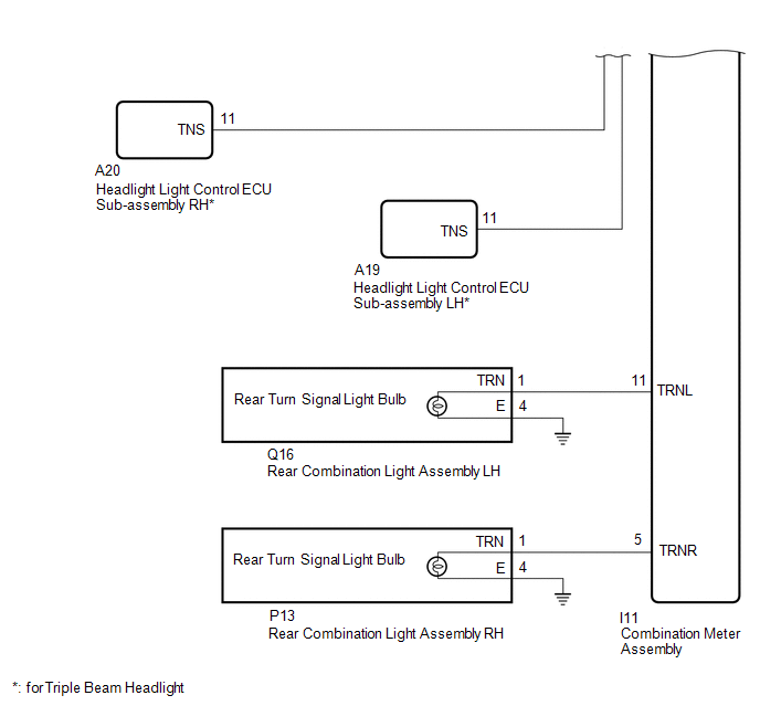
| 15. | CHECK HARNESS AND CONNECTOR (REAR COMBINATION LIGHT ASSEMBLY LH - COMBINATION METER ASSEMBLY AND BODY GROUND) |
(a) Disconnect the Q16 rear combination light assembly LH connector.
(b) Disconnect the I11 combination meter assembly connector.
(c) Measure the resistance according to the value(s) in the table below.
Standard Resistance:
| Tester Connection | Condition | Specified Condition |
|---|---|---|
| Q16-1 (TRN) - I11-11 (TRNL) | Always | Below 1 Ω |
| Q16-4 (E) - Body ground | Always | Below 1 Ω |
| Q16-1 (TRN) or I11-11 (TRNL) - Body ground | Always | 10 kΩ or higher |
| NG | | REPAIR OR REPLACE HARNESS OR CONNECTOR |
|
| 16. | CHECK REAR COMBINATION LIGHT ASSEMBLY LH |
(a) Remove the rear combination light assembly LH.
Click here
(b) Inspect the rear combination light assembly LH.
Click here
| OK | | REPLACE COMBINATION METER ASSEMBLY |
| NG | | REPLACE REAR COMBINATION LIGHT ASSEMBLY |
| 17. | CHECK HARNESS AND CONNECTOR (REAR COMBINATION LIGHT ASSEMBLY RH - COMBINATION METER ASSEMBLY AND BODY GROUND) |
(a) Disconnect the P13 rear combination light assembly RH connector.
(b) Disconnect the I11 combination meter assembly connector.
(c) Measure the resistance according to the value(s) in the table below.
Standard Resistance:
| Tester Connection | Condition | Specified Condition |
|---|---|---|
| P13-1 (TRN) - I11-5 (TRNR) | Always | Below 1 Ω |
| P13-4 (E) - Body ground | Always | Below 1 Ω |
| P13-1 (TRN) or I11-5 (TRNR) - Body ground | Always | 10 kΩ or higher |
| NG | | REPAIR OR REPLACE HARNESS OR CONNECTOR |
|
| 18. | CHECK REAR COMBINATION LIGHT ASSEMBLY RH |
(a) Remove the rear combination light assembly RH.
Click here
(b) Inspect the rear combination light assembly RH.
Click here
| OK | | REPLACE COMBINATION METER ASSEMBLY |
| NG | | REPLACE REAR COMBINATION LIGHT ASSEMBLY |
READ NEXT:
 Lost Communication with EV ECU (U0100,U0129,U0131,U0142,U0151,U0163,U0182,U023A)
DESCRIPTION DTC No. Detection Item DTC Detection Condition Trouble Area U0100 Lost Communication with EV ECU Both conditions are met:
IG voltage is 10.5 V or higher.
No communica
Speedometer Malfunction
DESCRIPTION The combination meter assembly receives vehicle speed signals from the brake booster with master cylinder assembly (skid control ECU) via the CAN communication line. The wheel speed sensor
Tachometer Malfunction
DESCRIPTION In this circuit, the combination meter assembly receives engine speed signals from the hybrid vehicle control ECU via the CAN communication system. The combination meter assembly displays
SEE MORE:
Parts Location
PARTS LOCATION ILLUSTRATION *1 AIR CONDITIONING CONTROL ASSEMBLY - REAR WINDOW DEFOGGER SWITCH *2 INSTRUMENT PANEL JUNCTION BLOCK ASSEMBLY - ECU-IG NO.1 FUSE - ECU-IG NO.3 FUSE *3 DLC3 - - ILLUSTRATION *1 DEFOGGER RELAY *2 AIR CONDITIONING AMPLIFIER ASSEMBLY *3
Back Camera Response Malfunction (C2A6A)
DESCRIPTION During self diagnosis of the parking assist ECU, the parking assist ECU sends display mode ID signals to the rear television camera assembly. This DTC is stored when the output of the rear television camera assembly does not match the expected output. DTC No. Detection Item DTC De
