Lexus NX: Parts Location
Lexus NX Service Manual / Vehicle Exterior / Window / Glass / Window Defogger System / Parts Location
PARTS LOCATION
ILLUSTRATION
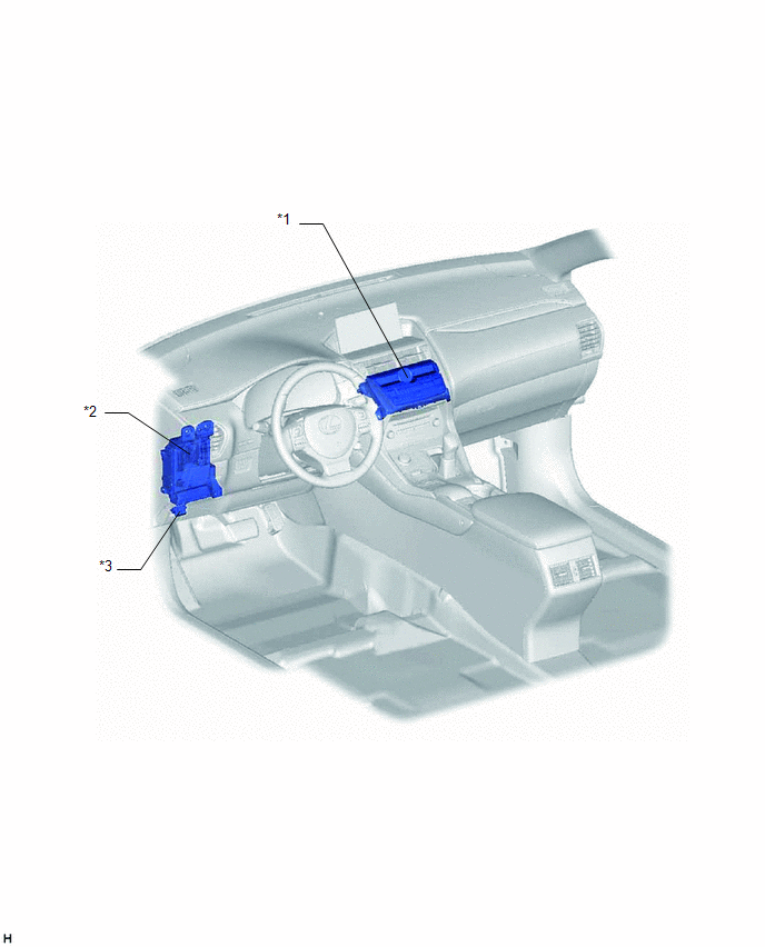
| *1 | AIR CONDITIONING CONTROL ASSEMBLY - REAR WINDOW DEFOGGER SWITCH | *2 | INSTRUMENT PANEL JUNCTION BLOCK ASSEMBLY - ECU-IG NO.1 FUSE - ECU-IG NO.3 FUSE |
| *3 | DLC3 | - | - |
ILLUSTRATION
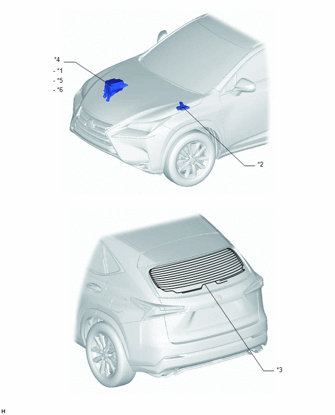
| *1 | DEFOGGER RELAY | *2 | AIR CONDITIONING AMPLIFIER ASSEMBLY |
| *3 | BACK DOOR GLASS - DEFOGGER WIRE | *4 | NO. 2 ENGINE ROOM RELAY BLOCK |
| *5 | DEF FUSE | *6 | ECU-B NO.2 FUSE |
READ NEXT:
 System Diagram
SYSTEM DIAGRAM Communication Table Transmitter Receiver Signal Communication Method Air Conditioning Control Assembly Air Conditioning Amplifier Assembly Rear window defogger switch
System Description
SYSTEM DESCRIPTION GENERAL (a) The rear window defogger wires are attached to the inside of the back door glass and defog the window surface quickly when the rear window defogger switch on the air con
How To Proceed With Troubleshooting
CAUTION / NOTICE / HINT
Use the following procedure to troubleshoot the window defogger system.
*: Use the Techstream.
PROCEDURE 1. VEHICLE BROUGHT TO WORKSHOP
NEXT
SEE MORE:
Inspection
INSPECTION PROCEDURE 1. INSPECT REAR HEADER SPEAKER ASSEMBLY (a) Measure the resistance according to the value(s) in the table below. Standard Resistance: Tester Connection Condition Specified Condition 1 - 2 Always 7.0 to 10.6 Ω If the result is not as specified, replace the
Precaution
PRECAUTION PRECAUTIONS WHEN USING TECHSTREAM (a) When using the Techstream with the vehicle power switch off, connect the Techstream to the DLC3 and turn a courtesy light switch on and off at intervals of 1.5 seconds or less until communication between the Techstream and the vehicle begins. Then sel
© 2016-2026 Copyright www.lexunx.com
