Lexus NX: Open or Short Circuit in Lock Switch Circuit (C13A3,C13AB)
DESCRIPTION
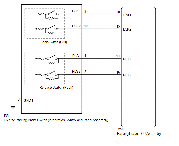
When the electric parking brake switch (integration control and panel assembly) is pulled to the lock side, a lock request signal is output to the parking brake ECU assembly.
| DTC No. | Detection Item | DTC Detection Condition | Trouble Area | Memory | Note |
|---|---|---|---|---|---|
| C13A3 | Open or Short Circuit in Lock Switch Circuit | All of following conditions are met:
HINT: *: When auxiliary battery voltage is 12 V |
| Yes | An electric parking brake system malfunction is displayed on the multi-information display. |
| C13AB | Lock Switch Circuit Comparison | Both of following conditions are met:
|
| Yes | An electric parking brake system malfunction is displayed on the multi-information display. |
WIRING DIAGRAM
CAUTION / NOTICE / HINT
NOTICE:
- Before disconnecting connectors or fuses, turn the power switch off and wait 20 seconds or more.
- When the electric parking brake switch (integration control and panel assembly) is pulled and held for 1 second or more without being pulled fully to the lock side, one of the 2 linked contacts may turn on while the other one turns off causing this DTC to be stored (system is not malfunctioning).
- When replacing the parking brake ECU assembly, operate the electric parking brake switch (integration control and panel assembly), as the parking brake indicator light (red) blinks when the power switch is first turned on (IG).
PROCEDURE
| 1. | INSPECT ELECTRIC PARKING BRAKE SWITCH (INTEGRATION CONTROL AND PANEL ASSEMBLY) |
(a) Remove the electric parking brake switch (integration control and panel assembly).
Click here .gif)
(b) Inspect the electric parking brake switch (integration control and panel assembly).
Click here
| NG | .gif) | REPLACE INTEGRATION CONTROL AND PANEL ASSEMBLY |
|
.gif)
| 2. | CHECK HARNESS AND CONNECTOR (PARKING BRAKE ECU ASSEMBLY - ELECTRIC PARKING BRAKE SWITCH (INTEGRATION CONTROL AND PANEL ASSEMBLY)) |
(a) Disconnect the I35 electric parking brake switch (integration control and panel assembly) connector.
(b) Disconnect the Q24 parking brake ECU assembly connector.
(c) Measure the resistance according to the value(s) in the table below.
Standard Resistance:
| Tester Connection | Condition | Specified Condition |
|---|---|---|
| Q24-20 (LCK1) - I35-9 (LOK1) | Always | Below 5 Ω |
| Q24-15 (LCK2) - I35-10 (LOK2) | Always | Below 5 Ω |
| Q24-20 (LCK1) or I35-9 (LOK1) - Body ground | Always | 10 kΩ or higher |
| Q24-15 (LCK2) or I35-10 (LOK2) - Body ground | Always | 10 kΩ or higher |
| I35-16 (GND1) - Body ground | Always | Below 5 Ω |
| NG | | REPAIR OR REPLACE HARNESS OR CONNECTOR |
|
| 3. | CHECK DTC |
(a) Clear the DTCs.
Click here
(b) Turn the power switch off.
(c) Turn the power switch on (IG).
(d) Perform a lock operation with the electric parking brake switch (integration control and panel assembly).
HINT:
When the electric parking brake switch (integration control and panel assembly) is pulled and held for 1 second or more without being pulled fully to the lock side, one of the 2 linked contacts may turn on while the other one turns off causing this DTC to be stored (system is not malfunctioning).
(e) Check for DTCs.
Click here
| DTC is output | | REPLACE PARKING BRAKE ECU ASSEMBLY |
| DTC is not output | | USE SIMULATION METHOD TO CHECK |
READ NEXT:
 Open or Short Circuit in Release Switch Circuit (C13A4,C13AC)
DESCRIPTION When the electric parking brake switch (integration control and panel assembly) is pushed to the release side, a release request signal is output to the parking brake ECU assembly. DTC
Open or Short Circuit in Motor (C13A6)
DESCRIPTION DTC No. Detection Item DTC Detection Condition Trouble Area Memory Note C13A6 Open or Short Circuit in Motor Both of following conditions are met:
Power switch on (
Actuator Malfunction (C13A7)
DESCRIPTION DTC No. Detection Item DTC Detection Condition Trouble Area Memory Note C13A7 Actuator Malfunction Both of following conditions are met:
Electric parking brake is o
SEE MORE:
Customize Parameters
CUSTOMIZE PARAMETERS CUSTOMIZE POWER WINDOW CONTROL SYSTEM HINT: The following items can be customized. NOTICE:
When the customer requests a change in a function, first make sure that the function can be customized.
Be sure to make notes of the current settings before customizing.
When troubl
Utility
UTILITY FREEZE FRAME DATA NOTICE:
Freeze frame data is stored and updated each time the brakes are operated. Only the latest 30 sets of data are stored.
Using the Techstream, make sure to save the data before performing a reproduction test as the data will be updated. HINT: The freeze frame dat
