Lexus NX: Open or Short Circuit in Motor (C13A6)
DESCRIPTION
| DTC No. | Detection Item | DTC Detection Condition | Trouble Area | Memory | Note |
|---|---|---|---|---|---|
| C13A6 | Open or Short Circuit in Motor | Both of following conditions are met:
|
| Yes | An electric parking brake system malfunction is displayed on the multi-information display. |
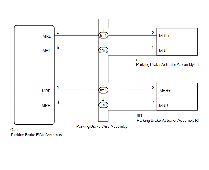
WIRING DIAGRAM
CAUTION / NOTICE / HINT
NOTICE:
- Before disconnecting connectors or fuses, turn the power switch off and wait 20 seconds or more.
- When replacing the parking brake ECU assembly, operate the electric parking brake switch (integration control and panel assembly), as the parking brake indicator light (red) blinks when the power switch is first turned on (IG).
PROCEDURE
| 1. | READ VALUE USING TECHSTREAM (RH ACTUATOR MOTOR MALFUNCTION(OPEN/SHORT) / LH ACTUATOR MOTOR MALFUNCTION(OPEN/SHORT)) |
(a) Turn the power switch off.
(b) Connect the Techstream to the DLC3.
(c) Turn the power switch on (IG) and the Techstream on.
(d) Enter the following menus: Chassis / Electric Parking Brake / Data List.
(e) Check the values by referring to the table below.
Chassis > Electric Parking Brake > Data List| Tester Display | Measurement Item | Range | Normal Condition |
|---|---|---|---|
| RH Actuator Motor Malfunction(Open/Short) | Parking brake motor RH (parking brake actuator assembly RH) open circuit or short circuit malfunction display | Detected Malfunction or No Detected Malfunction | No Detected Malfunction |
| LH Actuator Motor Malfunction(Open/Short) | Parking brake motor LH (parking brake actuator assembly LH) open circuit or short circuit malfunction display | Detected Malfunction or No Detected Malfunction | No Detected Malfunction |
| Tester Display |
|---|
| RH Actuator Motor Malfunction(Open/Short) |
| LH Actuator Motor Malfunction(Open/Short) |
|
.gif)
| 2. | INSPECT PARKING BRAKE WIRE ASSEMBLY NO.1 |
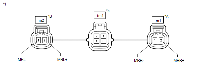
| *1 | Parking Brake Wire Assembly | - | - |
| *A | RH | *B | LH |
| *a | Male connector | - | - |
(a) Remove the parking brake wire assembly.
Click here .gif)
(b) Check the parking brake wire assembly for damage.
OK:
No damage.
HINT:
If damaged, there may be a short between the wire harnesses or a short to ground.
(c) Inspect the parking brake wire assembly.
Standard Resistance:
LH| Tester Connection | Condition | Specified Condition |
|---|---|---|
| tm1 (Male connector)-1 - m2-2 (MRL+) | Always | Below 1 Ω |
| tm1 (Male connector)-3 - m2-1 (MRL-) | Always | Below 1 Ω |
| tm1 (Male connector)-1 - m2-1 (MRL-) | Always | 10 kΩ or higher |
| tm1 (Male connector)-3 - m2-2 (MRL+) | Always | 10 kΩ or higher |
| tm1 (Male connector)-1 - tm1 (Male connector)-3 | Always | 10 kΩ or higher |
| tm1 (Male connector)-1 - tm1 (Male connector)-2 | Always | 10 kΩ or higher |
| tm1 (Male connector)-1 - tm1 (Male connector)-4 | Always | 10 kΩ or higher |
| tm1 (Male connector)-3 - tm1 (Male connector)-2 | Always | 10 kΩ or higher |
| tm1 (Male connector)-3 - tm1 (Male connector)-4 | Always | 10 kΩ or higher |
| Tester Connection | Condition | Specified Condition |
|---|---|---|
| tm1 (Male connector)-2 - m1-2 (MRR+) | Always | Below 1 Ω |
| tm1 (Male connector)-4 - m1-1 (MRR-) | Always | Below 1 Ω |
| tm1 (Male connector)-2 - m1-1 (MRR-) | Always | 10 kΩ or higher |
| tm1 (Male connector)-4 - m1-2 (MRR+) | Always | 10 kΩ or higher |
| tm1 (Male connector)-2 - tm1 (Male connector)-4 | Always | 10 kΩ or higher |
| tm1 (Male connector)-2 - tm1 (Male connector)-1 | Always | 10 kΩ or higher |
| tm1 (Male connector)-2 - tm1 (Male connector)-3 | Always | 10 kΩ or higher |
| tm1 (Male connector)-4 - tm1 (Male connector)-1 | Always | 10 kΩ or higher |
| tm1 (Male connector)-4 - tm1 (Male connector)-3 | Always | 10 kΩ or higher |
| NG | .gif) | REPLACE PARKING BRAKE WIRE ASSEMBLY NO.1 |
|
| 3. | CHECK HARNESS AND CONNECTOR (PARKING BRAKE ECU ASSEMBLY - PARKING BRAKE ACTUATOR ASSEMBLY) |
(a) Turn the power switch off.
(b) Make sure the parking brake wire assembly is securely installed.
(c) Disconnect the Q25 parking brake ECU assembly connector.
(d) Disconnect the m1 and/or m2 parking brake actuator assembly connector.
(e) Measure the resistance according to the value(s) in the table below.
Standard Resistance:
LH| Tester Connection | Condition | Specified Condition |
|---|---|---|
| Q25-4 (MRL+) - m2-2 (MRL+) | Always | Below 1 Ω |
| Q25-6 (MRL-) - m2-1 (MRL-) | Always | Below 1 Ω |
| Q25-4 (MRL+) or m2-2 (MRL+) - Body ground | Always | 10 kΩ or higher |
| Q25-6 (MRL-) or m2-1 (MRL-) - Body ground | Always | 10 kΩ or higher |
| Tester Connection | Condition | Specified Condition |
|---|---|---|
| Q25-1 (MRR+) - m1-2 (MRR+) | Always | Below 1 Ω |
| Q25-3 (MRR-) - m1-1 (MRR-) | Always | Below 1 Ω |
| Q25-1 (MRR+) or m1-2 (MRR+) - Body ground | Always | 10 kΩ or higher |
| Q25-3 (MRR-) or m1-1 (MRR-) - Body ground | Always | 10 kΩ or higher |
| NG | | REPAIR OR REPLACE HARNESS OR CONNECTOR |
|
| 4. | INSPECT PARKING BRAKE ACTUATOR ASSEMBLY |
(a) Inspect the parking brake actuator assembly.
Click here
| OK | | REPLACE PARKING BRAKE ECU ASSEMBLY |
| NG | | REPLACE PARKING BRAKE ACTUATOR ASSEMBLY |
READ NEXT:
 Actuator Malfunction (C13A7)
DESCRIPTION DTC No. Detection Item DTC Detection Condition Trouble Area Memory Note C13A7 Actuator Malfunction Both of following conditions are met:
Electric parking brake is o
Brake System Malfunction (C13A9)
DESCRIPTION The parking brake ECU assembly receives the wheel speed information of each wheel from the skid control ECU (brake booster with master cylinder assembly) via CAN communication. This DTC is
EPB High Temperature (C13AA)
DESCRIPTION If the electric parking brake is used continuously, the parking brake actuator assembly overheat prevention stops the system. This DTC is stored to protect the system and is not a malfunct
SEE MORE:
Removal
REMOVAL PROCEDURE 1. REMOVE CONSOLE ARMREST ASSEMBLY Click here 2. REMOVE UPPER REAR CONSOLE PANEL Click here 3. REMOVE UPPER NO. 2 CONSOLE PANEL GARNISH Click here 4. REMOVE INSTRUMENT SIDE PANEL LH Click here 5. REMOVE NO. 1 INSTRUMENT PANEL SAFETY PAD SUB-ASSEMBLY Click here 6
Foreign Object is Attached on Tip of Front Speed Sensor RH (C1235,C1236,C1238,C1239,C1275-C1278)
DESCRIPTION When foreign matter adheres to a speed sensor tip or speed sensor rotor, these DTCs are stored. The presence of foreign matter can be judged when an abnormal waveform is received from a sensor. These DTCs may also be detected when a malfunction occurs in the connector terminals or wire h
