Lexus NX: Operation Check
OPERATION CHECK
CHECK OUTER MIRROR SWITCH FUNCTION
(a) Turn the power switch on (ACC).
(b) With the mirror select switch set to L, check that the mirror surface moves up, down, left and right normally.
(c) With the mirror select switch set to R, check that the mirror surface moves up, down, left and right normally.
CHECK POWER RETRACTABLE MIRROR FUNCTION
(a) Turn the power switch on (ACC).
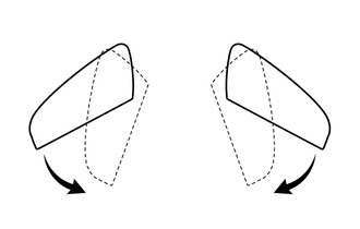
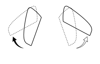
(b) When the outer rear view mirror assembly LH and outer rear view mirror assembly RH are in the driving position, press the mirror retract switch in the outer mirror switch assembly and check that they move to the retracted position.
HINT:
If both mirrors are moved to the driving/retracted position by hand, the mirrors will not retract/return with the first switch operation. Another switch operation is required to retract/return the mirrors.
(c) When the outer rear view mirror assembly LH and outer rear view mirror assembly RH are in the retracted position, press the mirror retract switch in the outer mirror switch assembly and check that they move to the driving position.
HINT:
If both mirrors are moved to the driving/retracted position by hand, the mirrors will not retract/return with the first switch operation. Another switch operation is required to retract/return the mirrors.
(d) When the outer rear view mirror assembly LH and outer rear view mirror assembly RH are in the driving position, move either of them forward by hand, and then press the mirror retract switch in the outer mirror switch assembly and check that both outer rear view mirror assemblies move to the retracted position.
(e) When the outer rear view mirror assembly LH and outer rear view mirror assembly RH are in the driving position, move either of them to the retracted position by hand, and then press the mirror retract switch in the outer mirror switch assembly and check that the other outer rear view mirror assembly moves to the retracted position.
(f) When the outer rear view mirror assembly LH and outer rear view mirror assembly RH are in the retracted position, move either of them to the driving position by hand, and then press the mirror retract switch in the outer mirror switch assembly and check that the other outer rear view mirror assembly moves to the driving position.
(g) While the outer rear view mirror assemblies are operating, stop either outer rear view mirror assembly by hand and check that its operation stops. Then press the mirror retract switch in the outer mirror switch assembly and check that the operation resumes.
CHECK AUTO POWER RETRACTABLE MIRROR FUNCTION
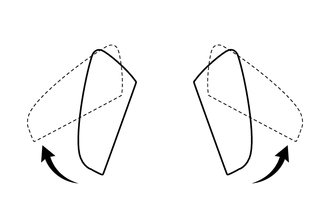
(a) When the power switch is off and the doors are unlocked by the entry, wireless or key-linked unlock functions or via the multiplex network master switch assembly, check that the outer rear view mirror assemblies move from the retracted position to the driving position and stop in the driving position.
HINT:
If the outer rear view mirror assemblies are retracted by pressing the mirror retract switch in the outer mirror switch assembly, the mirrors will not move to the driving position with the auto power retract mirror function.
(b) When the power switch is off and the doors are locked by the entry, wireless or key-linked lock functions or via the multiplex network master switch assembly, check that the outer rear view mirror assemblies move from the driving position to the retracted position and stop in the retracted position.
CHECK MEMORY AND REACTIVATION OPERATION

| *1 | SET Switch | *2 | M1 Switch |
| *3 | M2 Switch | *4 | M3 Switch |
HINT:
If the M1 switch, M2 switch and M3 switch are simultaneously pressed while the SET switch is pressed and held, the seat position will not be stored.
(a) Turn the power switch on (IG) and move the shift lever to P.
(b) Check the M1 switch.
(1) Using the outer mirror switch assembly, turn the mirror surface to the full left position.
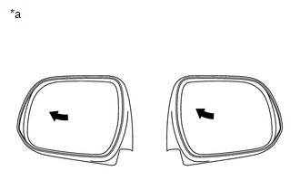
| *a | Turn to Left Fully |
(2) Check that the buzzer sounds for 0.5 seconds and the mirror surface position is memorized when the M1 switch is pressed within 3 seconds after the SET switch is pressed.
NOTICE:
- The mirror surface position will also be stored when the M1 switch is pressed after first pressing and holding the SET switch.
- The mirror surface position will not be stored when the SET switch and M1 switch are pressed simultaneously.
- The mirror surface position will not be stored when 2 or more of the seat memory switches are pressed simultaneously (for example, M1 and M2) after first pressing the SET switch.
(3) Using the outer mirror switch assembly, turn the mirror surface to the full right position.
(4) Press the M1 switch.
(5) Check that the buzzer sounds for 0.1 seconds and the outer mirror automatically moves to the memorized full left position.
(c) Check the M2 switch.
(1) Using the outer mirror switch assembly, turn the mirror surface to the full right position.
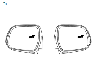
| *a | Turn to Right Fully |
(2) Check that the buzzer sounds for 0.5 seconds and the mirror surface position is memorized when the M2 switch is pressed within 3 seconds after the SET switch is pressed.
NOTICE:
- The mirror surface position will also be stored when the M2 switch is pressed after first pressing and holding the SET switch.
- The mirror surface position will not be stored when the SET switch and M2 switch are pressed simultaneously.
- The mirror surface position will not be stored when 2 or more of the seat memory switches are pressed simultaneously (for example, M1 and M2) after first pressing the SET switch.
(3) Using the outer mirror switch assembly, turn the mirror surface to the full left position.
(4) Press the M2 switch.
(5) Check that the buzzer sounds for 0.1 seconds and the outer mirror automatically moves to the memorized full right position.
(d) Check the M3 switch.
(1) Using the outer mirror switch assembly, turn the mirror surface to the full left position.
| *a | Turn to Left Fully |
(2) Check that the buzzer sounds for 0.5 seconds and the mirror surface position is memorized when the M3 switch is pressed within 3 seconds after the SET switch is pressed.
NOTICE:
- The mirror surface position will also be stored when the M3 switch is pressed after first pressing and holding the SET switch.
- The mirror surface position will not be stored when the SET switch and M3 switch are pressed simultaneously.
- The mirror surface position will not be stored when 2 or more of the seat memory switches are pressed simultaneously (for example, M2 and M3) after first pressing the SET switch.
(3) Using the outer mirror switch assembly, turn the mirror surface to the full right position.
(4) Press the M3 switch.
(5) Check that the buzzer sounds for 0.1 seconds and the outer mirror automatically moves to the memorized full left position.
(e) Check that switches M1, M2 and M3 cause the outer mirror to move to the recorded outer mirror positions under the following conditions: the power switch is turned off, the driver door is opened, and M1, M2 or M3 is pressed within 180 seconds.
(f) Check that switches M1, M2 and M3 cause the outer mirror to move to the recorded outer mirror positions under the following conditions: the power switch is turned off, the driver door is closed, and M1, M2 or M3 is pressed within 60 seconds.
CHECK REVERSE SHIFT-LINKED OPERATION OF MIRRORS
(a) Turn the power switch on (IG).
(b) Set the mirror select switch to L or R.
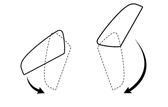
(c) Check that the mirror surface turns downward when the shift lever is moved to R.
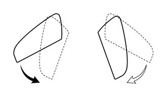
(d) Check that the mirror surface position returns to the original position when one of the following conditions is met:
- Shift lever is moved to any position other than R.
- Mirror select switch is in the neutral position (off).
- Power switch is turned off.
CHECK REVERSE SHIFT-LINKED MIRROR POSITION MEMORIZATION FUNCTION
(a) Turn the power switch on (IG).
(b) Set the mirror select switch to L or R.
(c) Check that the mirror surface turns downward when the shift lever is moved to R.
(d) While the mirror is in the reverse shift-linked operation position, move the mirror to the desired position.
(e) Check that the mirror moves to its normal position when the shift lever is moved to a different position from R, and then moves back to the memorized position when the shift lever is moved to R again.
CHECK MEMORY CALL FUNCTION
(a) Memory call function check.
(1) With a transmitter key recognition code registered:
With the recognition code of the transmitter registered in memory, perform an entry unlock or wireless unlock operation. Open the driver door and check that the front seat, steering wheel (tilt & telescopic) and outer mirror surface position automatically move to the positions memorized in memory.
(b) Memory registration.
(1) Prepare by memorizing the driving position through the seat memory switch (M1, M2 or M3).
(2) With the power switch on (IG), press and hold both of the following: a seat memory switch (M1, M2 or M3) and door control switch (LOCK or UNLOCK). Continue holding the switches until the answer-back buzzer sounds once (0.5 seconds).
NOTICE:
Do not bring 2 or more keys into the vehicle.
(c) Memory erasure.
(1) With the power switch on (IG), press and hold both of the following: the SET switch and door control switch (LOCK or UNLOCK). Continue holding the switches until the answer-back buzzer sounds twice (0.1 seconds each time).
NOTICE:
Do not bring 2 or more keys into the vehicle.
CHECK MEMORY CALL EMERGENCY STOP FUNCTION
(a) While a memory call function is operating, check that any one of the following actions will stop the memory call operation: 1) pressing the SET, M1, M2 or M3 switch, 2) moving the shift lever to R, 3) moving the mirror surface manually, or 4) moving the mirror surface to the uppermost, lowermost, leftmost or rightmost position.
CHECK MIRROR HEATER FUNCTION
(a) Turn the power switch on (IG).
(b) Check that pressing the rear window defogger switch (mirror heater switch) illuminates the indicator and warms the mirror surface.
(c) Check that after approximately 15 minutes, the indicator light turns off and the mirror heater deactivates.
HINT:
There is a timer extension function which can operate the mirror heater system for up to an additional 45 minutes.
CHECK AUTOMATIC GLARE-RESISTANT EC MIRROR FUNCTION
(a) Check that the automatic glare-resistant EC mirror function of the outer rear view mirror assembly operates when the automatic glare-resistant function of the inner rear view mirror assembly is operating.
READ NEXT:
 Customize Parameters
CUSTOMIZE PARAMETERS CUSTOMIZE POWER MIRROR CONTROL SYSTEM HINT: The following items can be customized. NOTICE:
When the customer requests a change in a function, first make sure that the function
Problem Symptoms Table
PROBLEM SYMPTOMS TABLE NOTICE: If the main body ECU (multiplex network body ECU) is replaced, refer to Registration. Click here HINT:
Use the table below to help determine the cause of problem
Terminals Of Ecu
TERMINALS OF ECU CHECK OUTER MIRROR CONTROL ECU ASSEMBLY LH (a) Disconnect the M5 ECU connector. (b) Measure the voltage and resistance according to the value(s) in the table below. Tester Connect
SEE MORE:
How To Proceed With Troubleshooting
CAUTION / NOTICE / HINT HINT:
Use the following procedure to troubleshoot the lighting system.
*: Use the Techstream.
PROCEDURE 1. VEHICLE BROUGHT TO WORKSHOP
NEXT 2. INSPECT AUXILIARY BATTERY VOLTAGE (a) Measure the auxiliary battery voltage with the power
Lost Communication with EMV (B1321)
DESCRIPTION DTC No. Detection Item DTC Detection Condition Trouble Area Memory B1321 Lost Communication with EMV
DTC Detection Condition: IG+ voltage 9.5 to 11.5 V or higher
Malfunction Status: Lost communication with radio receiver assembly
Malfunction Duration: 30 seconds
