- Power switch on (ACC)
- Outer rear view mirror assembly being retracted
Lexus NX: Terminals Of Ecu
Lexus NX Service Manual / Vehicle Exterior / Mirror (ext) / Power Mirror Control System (w/ Memory) / Terminals Of Ecu
TERMINALS OF ECU
CHECK OUTER MIRROR CONTROL ECU ASSEMBLY LH

(a) Disconnect the M5 ECU connector.
(b) Measure the voltage and resistance according to the value(s) in the table below.
| Tester Connection | Wiring Color | Terminal Description | Condition | Specified Condition |
|---|---|---|---|---|
| M5-5 (SIG) - M5-7 (GND) | GR - W-B | Power source | Power switch on (IG) | 11 to 14 V |
| Power switch off | Below 1 V | |||
| M5-6 (CPUB) - M5-7 (GND) | GR - W-B | Power source | Power switch off | 11 to 14 V |
| M5-14 (BDR) - M5-7 (GND) | Y - W-B | Power source | Power switch off | 11 to 14 V |
| M5-7 (GND) - Body ground | W-B - Body ground | Ground | Always | Below 1 Ω |
(c) Reconnect the M5 ECU connector.
(d) Measure the voltage according to the value(s) in the table below.
| Tester Connection | Wiring Color | Terminal Description | Condition | Specified Condition |
|---|---|---|---|---|
| B-3 (MR) - Body ground | SB - Body ground | Power retract mirror motor drive voltage | | 11 to 14 V |
| Below 1 V | |||
| B-11 (MF) - Body ground | LG - Body ground | Power retract mirror motor drive voltage |
| 11 to 14 V |
| Below 1 V | |||
| B-1 (MV) - Body ground | V - Body ground | Mirror motor drive voltage |
| Below 1 V |
| Below 1 V | |||
| 11 to 14 V | |||
| B-9 (MH) - Body ground | BR - Body ground | Mirror motor drive voltage |
| Below 1 V |
| Below 1 V | |||
| 11 to 14 V | |||
| B-10 (M+) - Body ground | R - Body ground | Mirror motor drive voltage |
| Below 1 V |
| Below 1 V | |||
| 11 to 14 V | |||
| B-4 (HTR+) - B-12 (TRN-) | B-G - W | Mirror heater drive voltage |
| 11 to 14 V |
| Below 1 V | |||
| B-5 (VDD) - B-14 (GND) | O - GR | Mirror position sensor power supply | Power switch on (IG) | 4.5 to 5.5 V |
| Power switch off | Below 1 V | |||
| B-6 (VSSR) - Body ground | W-B - Body ground | Vertical direction position sensor signal |
| Changes within range of 0 to 5 V |
| B-13 (HSSR) - Body ground | Y-B - Body ground | Horizontal direction position sensor signal |
| Changes within range of 0 to 5 V |
| M5-2 (M1) - M5-7 (GND) | G - W-B | Seat memory switch M1 signal |
| 11 to 14 V |
| Below 1 V | |||
| M5-3 (M2) - M5-7 (GND) | P - W-B | Seat memory switch M2 signal |
| 11 to 14 V |
| Below 1 V | |||
| M5-4 (M3) - M5-7 (GND) | B - W-B | Seat memory switch M3 signal |
| 11 to 14 V |
| Below 1 V | |||
| M5-1 (MM) - M5-7 (GND) | L - W-B | Seat memory switch SET signal |
| 11 to 14 V |
| Below 1 V |

CHECK OUTER MIRROR CONTROL ECU ASSEMBLY RH
(a) Disconnect the L5 ECU connector.
(b) Measure the voltage and resistance according to the value(s) in the table below.
| Tester Connection | Wiring Color | Terminal Description | Condition | Specified Condition |
|---|---|---|---|---|
| L5-5 (SIG) - L5-7 (GND) | P - W-B | Power source | Power switch on (IG) | 11 to 14 V |
| Power switch off | Below 1 V | |||
| L5-6 (CPUB) - L5-7 (GND) | B - W-B | Power source | Power switch off | 11 to 14 V |
| L5-14 (BDR) - L5-7 (GND) | LG - W-B | Power source | Power switch off | 11 to 14 V |
| L5-7 (GND) - Body ground | W-B - Body ground | Ground | Always | Below 1 Ω |
(c) Reconnect the L5 ECU connector.
(d) Measure the voltage according to the value(s) in the table below.
| Tester Connection | Wiring Color | Terminal Description | Condition | Specified Condition |
|---|---|---|---|---|
| A-3 (MR) - Body ground | SB - Body ground | Power retract mirror motor drive voltage |
| 11 to 14 V |
| Below 1 V | |||
| A-11 (MF) - Body ground | LG - Body ground | Power retract mirror motor drive voltage |
| 11 to 14 V |
| Below 1 V | |||
| A-1 (MV) - Body ground | V - Body ground | Mirror motor drive voltage |
| Below 1 V |
| Below 1 V | |||
| 11 to 14 V | |||
| A-9 (MH) - Body ground | BR - Body ground | Mirror motor drive voltage |
| Below 1 V |
| Below 1 V | |||
| 11 to 14 V | |||
| A-10 (M+) - Body ground | R - Body ground | Mirror motor drive voltage |
| Below 1 V |
| Below 1 V | |||
| 11 to 14 V | |||
| A-4 (HTR+) - A-12 (TRN-) | B-G - W | Mirror heater drive voltage |
| 11 to 14 V |
| Below 1 V | |||
| A-5 (VDD) - A-14 (GND) | O - GR | Mirror position sensor power supply | Power switch on (IG) | 4.5 to 5.5 V |
| Power switch off | Below 1 V | |||
| A-6 (VSSR) - Body ground | W-B - Body ground | Vertical direction position sensor signal |
| Changes within range of 0 to 5 V |
| A-13 (HSSR) - Body ground | Y-B - Body ground | Horizontal direction position sensor signal |
| Changes within range of 0 to 5 V |
CHECK MAIN BODY ECU (MULTIPLEX NETWORK BODY ECU)
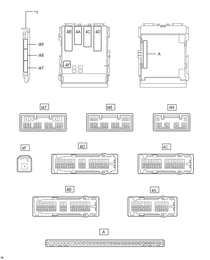
| *1 | Main Body ECU (Multiplex Network Body ECU) | - | - |
(a) Measure the voltage according to the value(s) in the table below.
| Tester Connection | Wiring Color | Terminal Description | Condition | Specified Condition |
|---|---|---|---|---|
| I49-4 (MIRB) - I49-6 (MIRE) | V - GR | Mirror surface adjust switch signal |
| Below 1.7 V |
| Below 2.7 V | |||
| Below 3.5 V | |||
| Below 4 V | |||
| 3.8 to 5 V | |||
| I49-5 (MIRS) - I49-6 (MIRE) | B - GR | Mirror select switch signal |
| Below 2 V |
| Below 1 V | |||
| 3.8 to 5 V | |||
| I47-14 (RET) - 4D-9 (GND1) | G - W-B | Mirror retract switch signal |
| Pulse generation (See waveform 1 or 2) |
| Below 1 V | |||
| I47-15 (RTR) - 4D-9 (GND1) | LG - W-B | Mirror retract switch signal |
| Pulse generation (See waveform 1 or 2) |
| Below 1 V |
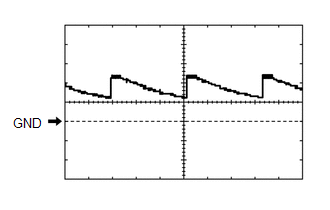
(b) Using an oscilloscope, check waveform 1.
Waveform 1 (Reference)| Item | Content |
|---|---|
| Terminal No. (Symbol) | I47-14 (RET) or I47-15 (RTR) - 4D-9 (GND1) |
| Tool Setting | 5 V/DIV., 20 ms/DIV. |
| Condition |
|
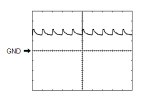
(c) Using an oscilloscope, check waveform 2.
Waveform 2 (Reference)| Item | Content |
|---|---|
| Terminal No. (Symbol) | I47-14 (RET) or I47-15 (RTR) - 4D-9 (GND1) |
| Tool Setting | 5 V/DIV., 20 ms/DIV. |
| Condition |
|
READ NEXT:
 Data List / Active Test
DATA LIST / ACTIVE TEST DATA LIST HINT: Using the Techstream to read the Data List allows the values or states of switches, sensors, actuators and other items to be read without removing any parts. Th
Driver Side Power Mirror cannot be Adjusted with Power Mirror Switch
DESCRIPTION When the outer mirror switch assembly mirror surface adjust switch (up/down/left/right) is operated, up/down/left/right signals are received by the main body ECU (multiplex network body EC
Front Passenger Side Power Mirror cannot be Adjusted with Power Mirror Switch
DESCRIPTION When the outer mirror switch assembly mirror surface adjust switch (up/down/left/right) is operated, up/down/left/right signals are received by the main body ECU (multiplex network body EC
SEE MORE:
Generator Control Module (P0A1A-151,P0A1C-709)
DESCRIPTION The MG ECU, which is built into the inverter with converter assembly, monitors its internal operation and will store DTCs if the system is malfunctioning. If any of the following DTCs are output, replace the inverter with converter assembly. DTC No. Detection Item DTC Detection Co
Disassembly
DISASSEMBLY PROCEDURE 1. REMOVE BACK DOOR UPPER OUTSIDE GARNISH LH (a) Remove the screw and back door upper outside garnish LH. 2. REMOVE BACK DOOR UPPER OUTSIDE GARNISH RH HINT: Use the same procedure described for the LH side. 3. REMOVE BACK DOOR NO. 1 GARNISH RETAINER (a) Remove
© 2016-2026 Copyright www.lexunx.com
