Lexus NX: Lost Communication with EMV (B1321)
DESCRIPTION
| DTC No. | Detection Item | DTC Detection Condition | Trouble Area | Memory |
|---|---|---|---|---|
| B1321 | Lost Communication with EMV |
|
| DTC stored |
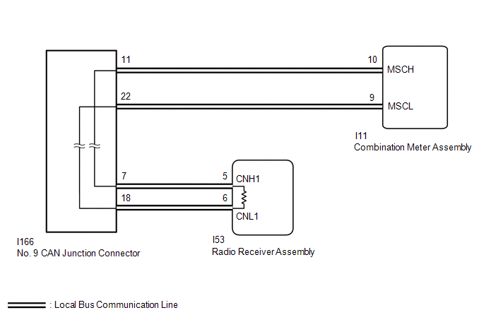
WIRING DIAGRAM
CAUTION / NOTICE / HINT
NOTICE:
-
After the power switch is turned off, there may be a waiting time before disconnecting the negative (-) battery terminal.
Click here
.gif)
-
When disconnecting the cable from the auxiliary negative (-) battery terminal while performing repairs, some systems need to be initialized after the cable is reconnected.
Click here
- When replacing the combination meter assembly, always replace it with a new one. If a combination meter assembly which was installed to another vehicle is used, the information stored in it will not match the information from the vehicle and a DTC may be stored.
-
The following malfunctions may occur if a radio receiver assembly from another vehicle is installed to this vehicle. Therefore, when replacing the radio receiver assembly, be sure to replace it with new one.
- Communication malfunction DTC is output
- Does not operate normally
HINT:
- B1321 will not continue to output when clear DTC is performed even if the malfunction continues.
-
Depending on the parts that are replaced during vehicle inspection or maintenance, performing initialization, registration or calibration may be needed.
Click here
PROCEDURE
| 1. | CHECK FOR DTC (NAVIGATION SYSTEM) |
(a) Check if navigation system DTCs are output.
Click here
| Result | Proceed to |
|---|---|
| Navigation system DTCs are not output. | A |
| Navigation system DTCs are output. | B |
| B | .gif) | GO TO NAVIGATION SYSTEM |
|
.gif)
| 2. | CHECK HARNESS AND CONNECTOR (NO. 9 CAN JUNCTION CONNECTOR - RADIO RECEIVER ASSEMBLY) |
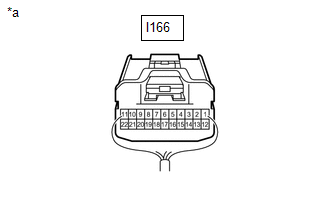
| *a | Rear view of wire harness connector (to No. 9 CAN Junction Connector) |
(a) Disconnect the No. 9 CAN junction connector.
(b) Measure the resistance according to the value(s) in the table below.
Standard Resistance:
| Tester Connection | Condition | Specified Condition |
|---|---|---|
| I166-7 - I166-18 | Cable disconnected from auxiliary negative (-) battery terminal | 108 to 132 Ω |
| NG | | GO TO STEP 5 |
|
| 3. | CHECK HARNESS AND CONNECTOR (NO. 9 CAN JUNCTION CONNECTOR - COMBINATION METER ASSEMBLY) |

| *a | Rear view of wire harness connector (to No. 9 CAN Junction Connector) |
(a) Measure the resistance according to the value(s) in the table below.
Standard Resistance:
| Tester Connection | Condition | Specified Condition |
|---|---|---|
| I166-8 - I166-19 | Cable disconnected from auxiliary negative (-) battery terminal | 200 Ω or higher |
| OK | | REPLACE NO. 9 CAN JUNCTION CONNECTOR |
|
| 4. | CHECK HARNESS AND CONNECTOR (NO. 9 CAN JUNCTION CONNECTOR - COMBINATION METER ASSEMBLY) |
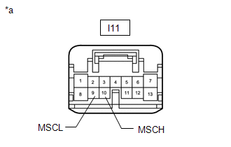
| *a | Front view of wire harness connector (to Combination Meter Assembly Connector) |
(a) Disconnect the combination meter assembly connector.
(b) Reconnect the I166 No. 9 CAN junction connector.
(c) Measure the resistance according to the value(s) in the table below.
Standard Resistance:
| Tester Connection | Condition | Specified Condition |
|---|---|---|
| I11-10 (MSCH) - I11-9 (MSCL) | Cable disconnected from auxiliary negative (-) battery terminal | 54 to 69 Ω |
| OK | | REPLACE COMBINATION METER ASSEMBLY |
| NG | | REPAIR OR REPLACE HARNESS OR CONNECTOR |
| 5. | CHECK HARNESS AND CONNECTOR (RADIO RECEIVER ASSEMBLY - NO. 9 CAN JUNCTION CONNECTOR) |
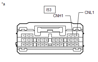
| *a | Front view of wire harness connector (to Radio Receiver Assembly Connector) |
(a) Disconnect the radio receiver assembly connector.
(b) Reconnect the I166 No. 9 CAN junction connector.
(c) Measure the resistance according to the value(s) in the table below.
Standard Resistance:
| Tester Connection | Condition | Specified Condition |
|---|---|---|
| I53-5(CNH1) - I53-6(CNL1) | Cable disconnected from auxiliary negative (-) battery terminal | 108 to 132 Ω |
| OK | | REPLACE RADIO RECEIVER ASSEMBLY |
| NG | | REPAIR OR REPLACE HARNESS OR CONNECTOR |
READ NEXT:
 Lost Communication with Clock Device (Local-CAN) (B1326)
DESCRIPTION DTC No. Detection Item DTC Detection Condition Trouble Area Memory B1326 Lost Communication with Clock Device (Local-CAN) After the radio receiver assembly receives a re
Fuel Sender Open Detected (B1500)
DESCRIPTION This DTC is stored when the combination meter detects a fuel sender gauge malfunction. DTC No. Detection Item DTC Detection Condition Trouble Area B1500 Fuel Sender Open Det
Open in Turn Signal Circuit (B1507,B1508)
DESCRIPTION These DTCs are stored when the combination meter assembly detects an open in a turn signal light circuit, a short in a turn signal light circuit, or a short in the hazard warning light cir
SEE MORE:
On-vehicle Inspection
ON-VEHICLE INSPECTION PROCEDURE 1. CHECK AUXILIARY BATTERY (a) Check that the auxiliary battery cables are connected to the correct terminals. HINT: If they are not, connect them properly. (b) Check the auxiliary battery for damage and deformation. HINT: If severe damage, deformation or leakage is f
Removal
REMOVAL CAUTION / NOTICE / HINT HINT:
Use the same procedure for the RH and LH sides.
The procedure listed below is for the LH side.
PROCEDURE 1. REMOVE REAR WIPER ARM HEAD CAP Click here 2. REMOVE REAR WIPER ARM AND BLADE ASSEMBLY Click here 3. REMOVE REAR WIPER MOTOR GROMMET Click here
