Lexus NX: Panel Switches do not Function
CAUTION / NOTICE / HINT
NOTICE:
When replacing the radio receiver assembly, always replace it with a new one.
If a radio receiver assembly which was installed to another vehicle is used, the following may occur:
- A communication malfunction DTC may be stored.
- The radio receiver assembly may not operate normally.
HINT:
Depending on the parts that are replaced during vehicle inspection or maintenance, performing initialization, registration or calibration may be needed. Refer to Precaution for Audio and Visual System.
Click here .gif)
PROCEDURE
| 1. | CHECK PANEL SWITCH |
(a) Check for foreign matter around the switches that might prevent operation.
OK:
No foreign matter is found.
| NG | .gif) | REMOVE ANY FOREIGN MATTER FOUND |
|
.gif)
| 2. | CHECK PANEL SWITCH (OPERATION CHECK) |
| (a) Enter the "Panel & Steering Switch Check Mode" screen. Refer to Check Panel & Steering Switch in Operation Check. Click here |
|
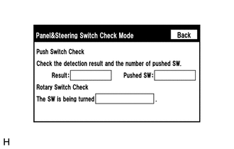
(b) Operate the abnormal switch and check if the switch status is correctly displayed.
OK:
The switch status is correctly displayed as operated.
| OK | | REPLACE RADIO RECEIVER ASSEMBLY |
| NG | | PROCEED TO NEXT SUSPECTED AREA SHOWN IN PROBLEM SYMPTOMS TABLE |
READ NEXT:
 Screen Flicker or Color Distortion
PROCEDURE 1. CHECK DISPLAY SETTING (a) Reset display settings (contrast, brightness) and check that the screen appears normal. OK: The display returns to normal. OK END (DISPLAY SETTIN
Poor Sound Quality in All Modes (Low Volume)
PROCEDURE 1. CHECK AUDIO SETTINGS (a) Set treble, middle and bass to the initial values and check that the sound is normal. OK: The sound returns to normal. HINT: Sound quality adjustment me
"No GPS signal" mark is displayed
CAUTION / NOTICE / HINT NOTICE: When replacing the radio receiver assembly, always replace it with a new one. If a radio receiver assembly which was installed to another vehicle is used, the following
SEE MORE:
Installation
INSTALLATION PROCEDURE 1. INSTALL BACK DOOR LOCK ASSEMBLY (w/ Power Back Door) NOTICE:
When installing a new back door lock assembly, if there is any tape stuck to it, remove the tape.
When installing a new back door lock assembly, if there are any strings attached to it, cut the strings off.
Diagnosis System
DIAGNOSIS SYSTEM SYMPTOM SIMULATION HINT: The most difficult case in troubleshooting is when no problem symptoms occur. In such a case, a thorough problem analysis must be carried out. A simulation of the same or similar conditions and environment in which the problem occurred in the customer's vehi
