Lexus NX: Diagnosis System
DIAGNOSIS SYSTEM
SYMPTOM SIMULATION
HINT:
The most difficult case in troubleshooting is when no problem symptoms occur. In such a case, a thorough problem analysis must be carried out. A simulation of the same or similar conditions and environment in which the problem occurred in the customer's vehicle should be carried out. No matter how much skill or experience a technician has, troubleshooting without confirming the problem symptoms will lead to important repairs being overlooked and mistakes or delays.
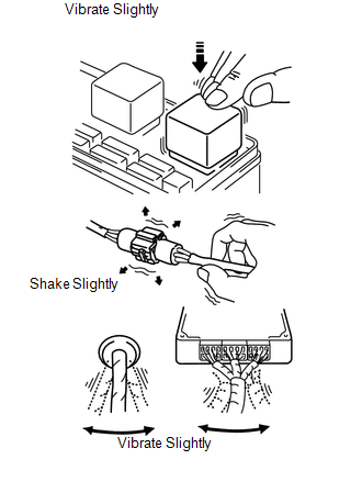
(a) Vibration method: When vibration seems to be the major cause.
HINT:
Perform the simulation method only during the primary check period (for approximately 6 seconds after the power switch is turned on [IG]).
(1) Slightly vibrate the part of the sensor considered to be the cause of the problem with your fingers and check whether the malfunction occurs.
NOTICE:
Shaking the relays too strongly may result in open relays.
(2) Slightly shake the connector vertically and horizontally.
(3) Slightly shake the wire harness vertically and horizontally.
HINT:
The connector joint and fulcrum of the vibration are the major areas to be checked thoroughly.
FUNCTION OF SRS WARNING LIGHT
(a) Primary check.
(1) Turn the power switch off. Wait for at least 2 seconds, and then turn the power switch on (IG). The SRS warning light comes on for approximately 6 seconds and diagnosis of the airbag system (including the seat belt pretensioners) is performed.
HINT:
If trouble is detected during the primary check, the SRS warning light remains on even after the primary check period (of approximately 6 seconds) has elapsed.
(b) Constant check.
(1) After the primary check, the airbag ECU assembly constantly monitors the airbag system for trouble.
HINT:
If trouble is detected during the constant check, the airbag ECU assembly functions as follows:
- The SRS warning light comes on.
- The SRS warning light goes off, and then comes on. This blinking pattern indicates a source voltage drop. The SRS warning light goes off 10 seconds after the source voltage returns to normal.
(c) Review.
(1) When the airbag system is normal:
The SRS warning light comes on only during the primary check period (for approximately 6 seconds after the power switch is turned on [IG]).
(2) When the airbag system has trouble:
- The SRS warning light remains on even after the primary check period has elapsed.
- The SRS warning light goes off after the primary check, but comes on again during the constant check.
- The SRS warning light does not come on when turning the power switch from off to on (IG).
HINT:
The airbag ECU assembly functions to keep the SRS warning light on if the airbag has been deployed.
CHECK SRS WARNING LIGHT
(a) Turn the power switch on (IG) and check that the SRS warning light comes on for approximately 6 seconds (primary check).
(b) Check that the SRS warning light goes off approximately 6 seconds after the power switch is turned to on (IG) (constant check).
HINT:
When any of the following symptoms occur, refer to the "Problem Symptoms Table".
Click here .gif)
- The SRS warning light comes on occasionally after the primary check period has elapsed.
- The SRS warning light comes on, but a DTC is not output.
- The power switch is turned from off to on (IG), but the SRS warning light does not come on.
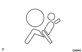
FUNCTION OF PASSENGER AIRBAG ON/OFF INDICATOR
(a) Initial check
(1) Turn the power switch on (IG).
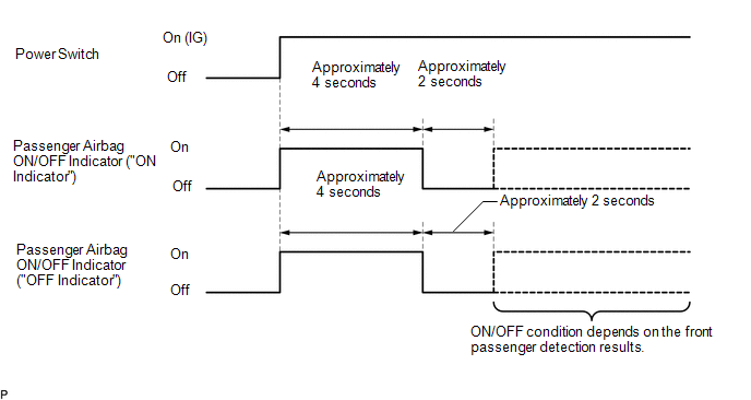
(2) The passenger airbag ON/OFF indicator comes on for approximately 4 seconds, and then goes off for approximately 2 seconds.
(3) Approximately 6 seconds after the power switch is turned to ON, the passenger airbag ON/OFF indicator will be on or off depending on the conditions listed below.
| Condition | "ON" Indicator | "OFF" Indicator |
|---|---|---|
| Vacant | Off | On |
| Adult is seated | On | Off |
| Child is seated | Off | On |
| Front passenger occupant classification failure | Off | On |
HINT:
- The timing chart below shows the operation of the passenger airbag ON/OFF indicator. Use the chart to check the indicator light circuit.
- When the occupant classification system has trouble, both the SRS warning light and passenger airbag ON/OFF indicator ("OFF") come on. In this case, check for DTCs for "Airbag System" first. Then troubleshoot the occupant classification system if DTC B1650/32 is output, and troubleshoot the passenger airbag ON/OFF indicator if DTC B1660/43 is output.
CHECK PASSENGER AIRBAG ON/OFF INDICATOR
(a) Turn the power switch on (IG).

(b) Check that the passenger airbag ON/OFF indicator ("ON" and "OFF") comes on for approximately 4 seconds, and then goes off for approximately 2 seconds.
HINT:
In order to check the operation of the passenger airbag ON/OFF indicator when approximately 6 seconds have elapsed after turning the power switch on (IG), refer to the table in the previous step.
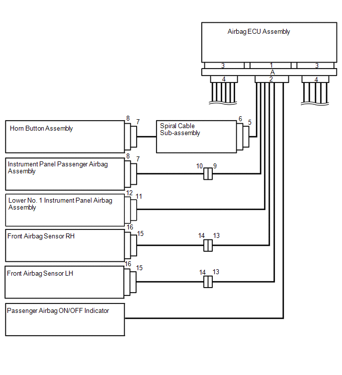
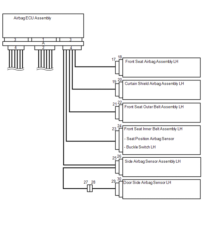
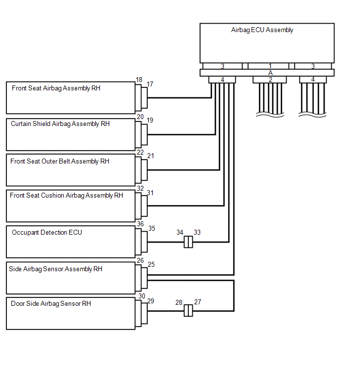
FUNCTION OF SRS CONNECTORS
(a) SRS connectors are located as shown in the illustration.
| Connector Type | Application |
|---|---|
| Terminal Twin-Lock Mechanism | Connectors 5, 13, 24, 26, 27 |
| Half Connection Prevention Mechanism | Connectors 5, 31 |
| Activation Prevention Mechanism | Connectors 2, 4, 6, 8, 10, 12, 18, 20, 22, 32 |
| Connector Lock Mechanism (1) | Connectors 7, 11, 19, 21 |
| Connector Position Assurance Mechanism | Connectors 14, 15, 17, 25, 28, 29 |
| Connector Lock Mechanism (2) | Connectors A |
| Improper Connection Prevention Lock Mechanism | Connectors A |
(b) Terminal twin-lock mechanism
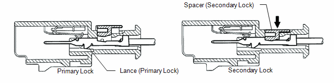
(1) This mechanism is designed to increase the ability of the terminal to remain connected and prevent it from accidentally being disconnected.
(2) The connector has a two-piece construction consisting of the housing and spacer to securely lock the terminal using both the lance (primary lock) and spacer (secondary lock).
(c) Half connection prevention mechanism
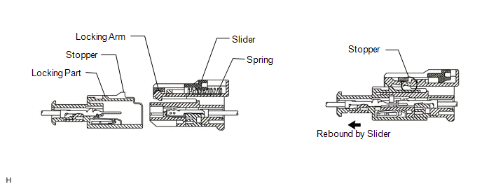
(1) This mechanism is designed to prevent the connector from being connected only halfway.
(2) If the connector is not completely connected, the connector is disconnected by the force of the spring so that no continuity exists.
(d) Activation prevention mechanism
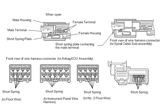
(1) The activation prevention mechanism is designed to create a short circuit automatically between the positive (+) and negative (-) terminals of an airbag power source connector when disconnected.
(2) The short spring plate contained in the connector creates a closed circuit on the airbag side (no potential difference can occur between both terminals), preventing accidental airbag deployment when servicing.
(e) Connector lock mechanism (1)
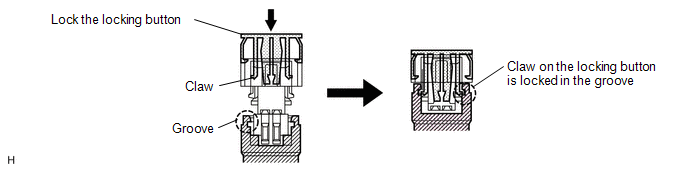
(1) This mechanism is designed to prevent the connector from accidentally being disconnected.
(2) Locking the connector locking button engages the locking button claw in the groove of the other connector to connect the connector securely.
(f) Connector Position Assurance (CPA) mechanism
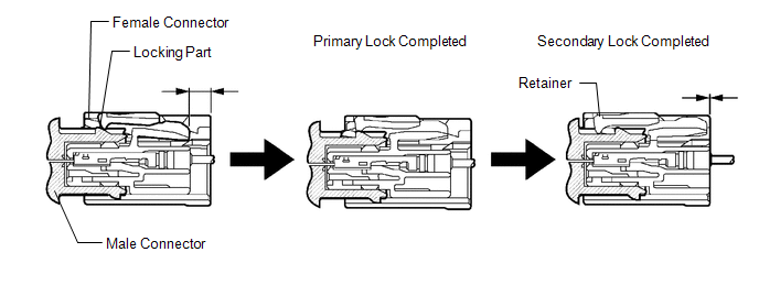
(1) This mechanism is designed to detect when the connector is connected only halfway.
(2) The CPA and female connector slide to the male connector side at the same time and the primary lock is completed when the female connector is engaged with the male connector. From this point, only the CPA slides to the male connector side. The secondary lock is completed when the CPA retainer is engaged with the female connector. When the CPA and female connector ends are aligned, the connectors are completely engaged.
(g) Connector lock mechanism (2)
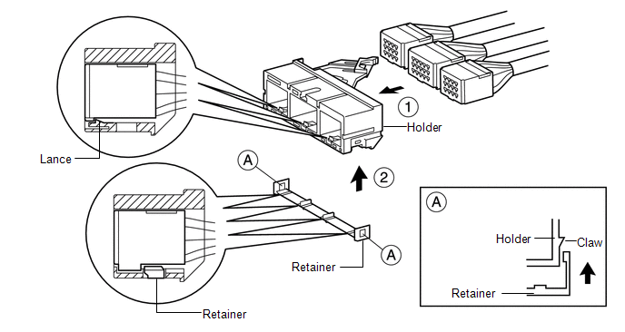
(1) This mechanism is designed to prevent the connector from accidentally being disconnected.
(2) Sliding the connector all the way into the holder and locking the lance completes the primary lock.
(3) Engaging the retainer with the holder as shown in the illustration completes the secondary lock, preventing the connector from accidentally being disconnected.
(h) Improper connection prevention lock mechanism
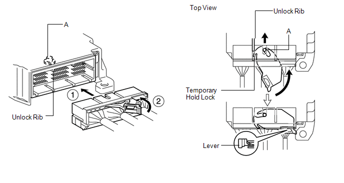
(1) This mechanism is designed to prevent the connector from being connected only halfway.
(2) When the holder is connected to the airbag ECU assembly, the unlock rib unlocks the temporary hold lock, allowing the lever to be pushed in by rotating around the A axis.
(3) Locking the lever to the holder locks the holder securely.
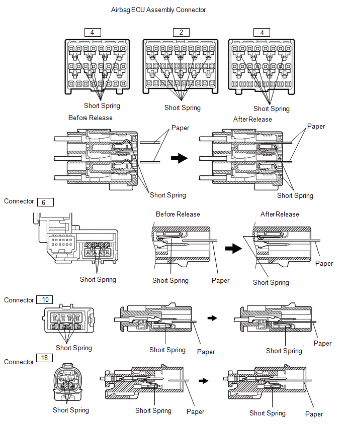
ACTIVATION PREVENTION MECHANISM
(a) Function of activation prevention mechanism
(1) An activation prevention mechanism is built into the connector (on the airbag ECU assembly side) of the airbag system squib circuit to prevent accidental airbag activation.
(2) This mechanism closes the circuit when the connector is disconnected by bringing the short spring into contact with the terminals and insulating the circuit from external power sources to prevent accidental airbag activation.
(b) Releasing of activation prevention mechanism
(1) To release the activation prevention mechanism, insert a piece of paper with the same thickness as the male terminal (approximately 0.5 mm [0.0197 in.]) between the terminals and short spring to break the connection.
(2) Refer to the following illustrations concerning connectors utilizing the activation prevention mechanism and its release method.
CAUTION:
Never release the activation prevention mechanism on the squib connector even when inspecting with the squib disconnected.
NOTICE:
- Do not release the activation prevention mechanism unless specially directed by the troubleshooting procedure.
- To prevent the terminal and short spring from being damaged, always use a piece of paper with the same thickness as the male terminal.
READ NEXT:
 Dtc Check / Clear
DTC CHECK / CLEAR CHECK DTC (a) Turn the power switch off. (b) Connect the Techstream to the DLC3. (c) Turn the power switch on (IG). (d) Turn the Techstream on. (e) Enter the following menus: Body El
Check Mode Procedure
CHECK MODE PROCEDURE NOTICE: Enter "Signal Check" from the "DTC Check" screen displayed on the Techstream to clear the output DTCs (both present and past). HINT:
DTCs can be stored more sensitively
Data List / Active Test
DATA LIST / ACTIVE TEST READ DATA LIST HINT: Using the Techstream to read the Data List allows the values or states of switches, sensors, actuators and other items to be read without removing any part
SEE MORE:
ECU Malfunction (C1614)
DESCRIPTION This DTC is stored if the parking assist ECU judges that there is an internal malfunction as a result of its self check. HINT: The parking assist ECU stores different types of information during initialization. If the parking assist ECU cannot read the stored information when activated,
Terminals Of Ecu
TERMINALS OF ECU CHECK CERTIFICATION ECU (SMART KEY ECU ASSEMBLY) (a) Disconnect the I53 certification ECU (smart key ECU assembly) connector. (b) Measure the voltage and resistance according to the value(s) in the table below. Tester Connection Input/Output Wiring Color Terminal Descripti
