Lexus NX: Parts Location
Lexus NX Service Manual / Engine & Hybrid System / Cruise Control / Front Camera System / Parts Location
PARTS LOCATION
ILLUSTRATION
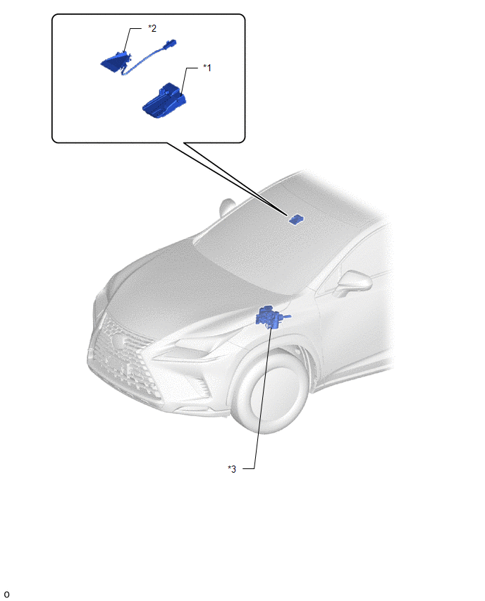
| *1 | FORWARD RECOGNITION CAMERA | *2 | FORWARD RECOGNITION WITH HEATER HOOD SUB-ASSEMBLY |
| *3 | BRAKE BOOSTER WITH MASTER CYLINDER ASSEMBLY - SKID CONTROL ECU | - | - |
ILLUSTRATION
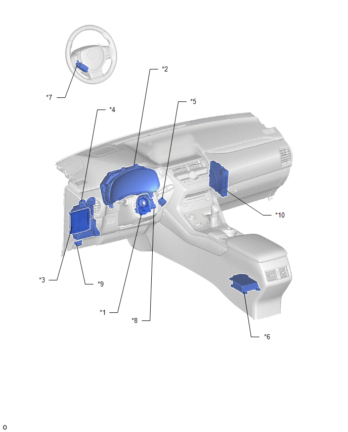
| *1 | STEERING SENSOR | *2 | COMBINATION METER ASSEMBLY |
| *3 | MULTIPLEX NETWORK BODY ECU - MAIN BODY ECU | *4 | INSTRUMENT PANEL JUNCTION BLOCK ASSEMBLY - ECU-IG NO.2 FUSE |
| *5 | SKID CONTROL BUZZER | *6 | AIRBAG ECU ASSEMBLY |
| *7 | STEERING VIBRATION ECU | *8 | SPIRAL CABLE SUB-ASSEMBLY |
| *9 | DLC3 | *10 | HYBRID VEHICLE CONTROL ECU |
READ NEXT:
 System Diagram
SYSTEM DIAGRAM
How To Proceed With Troubleshooting
CAUTION / NOTICE / HINT HINT:
Before troubleshooting the front camera system, first refer to How to Proceed with Troubleshooting for the pre-collision system.
Click here
If a message is display
Utility
UTILITY NOTICE:
If the forward recognition camera has been replaced with a new one or the windshield glass has been removed and installed, it is necessary to perform forward recognition camera adju
SEE MORE:
Startability Malfunction (P1604)
DESCRIPTION If the engine does not start or it takes a long time for the engine to start, despite the ECM receiving the engine start request signal from the hybrid vehicle control ECU via CAN communication, this DTC will be stored. Read freeze frame data using the Techstream. The ECM records vehicle
Dtc Check / Clear
DTC CHECK / CLEAR CHECK FOR DTC (a) Connect the Techstream to the DLC3. (b) Turn the power switch on (IG). (c) Turn the Techstream on. (d) Enter the following menus: Body Electrical / Main body / Trouble Codes. Body Electrical > Main Body > Trouble Codes (e) Body Electrical / Front Recognition
© 2016-2026 Copyright www.lexunx.com
