Lexus NX: Parts Location
PARTS LOCATION
ILLUSTRATION
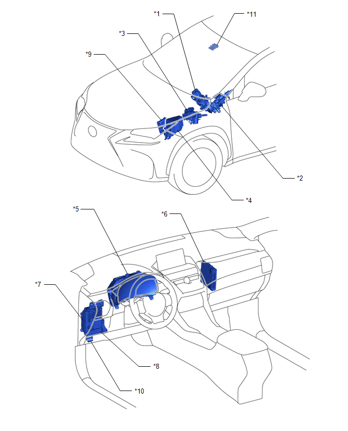
| *1 | POWER STEERING ECU ASSEMBLY - POWER STEERING MOTOR | *2 | ELECTRIC POWER STEERING COLUMN SUB-ASSEMBLY - TORQUE SENSOR |
| *3 | SKID CONTROL ECU (BRAKE BOOSTER WITH MASTER CYLINDER ASSEMBLY) | *4 | NO. 1 ENGINE ROOM RELAY BLOCK - EPS FUSE |
| *5 | COMBINATION METER ASSEMBLY - POWER STEERING WARNING LIGHT | *6 | HYBRID VEHICLE CONTROL ECU |
| *7 | MAIN BODY ECU (MULTIPLEX NETWORK BODY ECU) | *8 | INSTRUMENT PANEL JUNCTION BLOCK ASSEMBLY - EPS-IG FUSE |
| *9 | ECM | *10 | DLC3 |
| *11 | FORWARD RECOGNITION CAMERA | - | - |
READ NEXT:
 System Diagram
SYSTEM DIAGRAM
System Description
SYSTEM DESCRIPTION
The power steering system generates torque through the operation of the motor and the reduction gear installed on the column shaft in order to assist steering effort.
The power
How To Proceed With Troubleshooting
CAUTION / NOTICE / HINT HINT:
Use these procedures to troubleshoot the power steering system.
*: Use the Techstream.
PROCEDURE 1. VEHICLE BROUGHT TO WORKSHOP
NEXT
SEE MORE:
A/C Inverter Low Voltage Power Resource System Malfunction (B1477)
DESCRIPTION The compressor with motor assembly monitors the inverter control power voltage in the circuit. The hybrid vehicle control ECU stops the compressor control and stores this DTC when the monitored voltage is outside the specified range. This DTC will be stored as a history DTC. Compressor c
Switch Lights of Remote Touch Always Illuminate or cannot be Controlled Using Rheostat
DESCRIPTION Power is supplied to the remote touch illumination when the light control switch is in the tail or head position. HINT:
When the remote touch is in self check mode, the switch illumination on the remote touch may remain on.
If any illumination controlled by the rheostat switch has a
© 2016-2026 Copyright www.lexunx.com
