Lexus NX: Parts Location
Lexus NX Service Manual / Steering / Steering Column / Heated Steering Wheel System / Parts Location
PARTS LOCATION
ILLUSTRATION
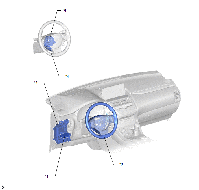
| *1 | NO. 2 COMBINATION SWITCH ASSEMBLY - STEERING HEATER SWITCH | *2 | STEERING WHEEL ASSEMBLY - STEERING WHEEL HEATER UNIT |
| *3 | INSTRUMENT PANEL JUNCTION BLOCK ASSEMBLY - ECU-IG NO. 2 FUSE - ECU-IG NO. 3 FUSE | *4 | STEERING VIBRATION AND HEATER ECU |
| *5 | SPIRAL WITH SENSOR CABLE SUB-ASSEMBLY | - | - |
ILLUSTRATION
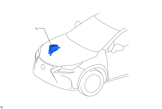
| *1 | NO. 2 ENGINE ROOM RELAY BLOCK - STRG HTR RELAY - STRG HTR FUSE | - | - |
READ NEXT:
 System Diagram
SYSTEM DIAGRAM SYSTEM DIAGRAM
System Description
SYSTEM DESCRIPTION HEATED STEERING WHEEL SYSTEM (a) The heated steering wheel system heats the steering wheel assembly when the steering heater switch is operated. (b) The heated steering wheel system
How To Proceed With Troubleshooting
CAUTION / NOTICE / HINT HINT: Use these procedures to troubleshoot the heated steering wheel system. PROCEDURE 1. VEHICLE BROUGHT TO WORKSHOP
NEXT 2. INSPECT AUXILIARY
SEE MORE:
Removal
REMOVAL CAUTION / NOTICE / HINT CAUTION: Wear protective gloves. Sharp areas on the parts may injure your hands. HINT:
Use the same procedure for the RH and LH sides.
The procedure listed below is for the LH side.
PROCEDURE 1. PRECAUTION CAUTION: Be sure to read Precaution thoroughly before
Front Wiper Rubber
ComponentsCOMPONENTS ILLUSTRATION *1 FRONT WIPER BLADE LH *2 WIPER RUBBER LH ReplacementREPLACEMENT CAUTION / NOTICE / HINT HINT:
Use the same procedure for RHD and LHD vehicles.
The procedure listed below is for LHD vehicles.
Use the same procedure for the RH and LH si
© 2016-2026 Copyright www.lexunx.com
