Lexus NX: MOST Communication Malfunction (B15D0)
DESCRIPTION
Navigation system components communicate with each other via MOST communication.
If a line short or short to ground occurs in a MOST communication line, communication will not be possible and the navigation system will not operate normally.
After the power switch is turned on (ACC), if the MOST communication network cannot be established and MOST communication is determined to not be possible, this DTC will be stored.
HINT:
Electrical noise may cause communication malfunctions between devices in the MOST network.
| DTC No. | Detection Item | DTC Detection Condition | Trouble Area |
|---|---|---|---|
| B15D0 | MOST Communication Malfunction | MOST network cannot be established. |
|
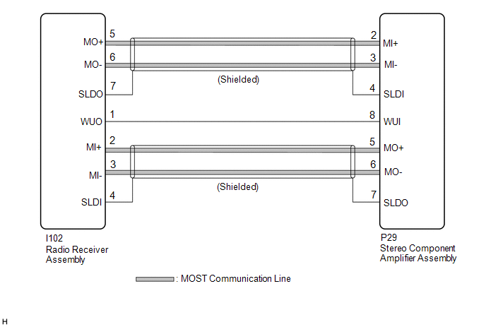
WIRING DIAGRAM
CHECK POINT
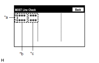
- Before proceeding with the following procedure, start diagnostic mode, enter the "MOST Line Check" screen and check the results.
- The following MOST line check result pattern table can be used to quickly identify trouble areas and inspection procedures.
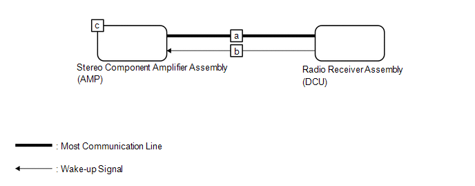 MOST Line Check Result Pattern
 | Pattern | Device Name | Result | Trouble Area | Inspection |
|---|---|---|---|---|
| 1 | DCU | OK | a, c | Inspect MOST communication line between "DCU" and "AMP" |
| AMP | OK | |||
| 2 | DCU | OK | b, c | Inspect wake up communication line between "DCU" and "AMP" |
| AMP | NCON |
CAUTION / NOTICE / HINT
NOTICE:
-
Depending on the parts that are replaced during vehicle inspection or maintenance, performing initialization, registration or calibration may be needed. Refer to Precaution for Navigation System.
Click here
.gif)
-
When replacing the radio receiver assembly, always replace it with a new one. If a radio receiver assembly which was installed to another vehicle is used, the following may occur:
- A communication malfunction DTC may be stored.
- The radio receiver assembly may not operate normally.
PROCEDURE
| 1. | CHECK DTC |
(a) Check for DTCs.
Body Electrical > Navigation System > Trouble Codes| Result | Proceed to |
|---|---|
| DTC B15C3 and B15D3 are not output | A |
| DTC B15C3 is output | B |
| DTC B15D3 is output | C |
HINT:
-
If a short occurs in a speaker circuit, the sound output from the speakers will become very low or will stop and DTC B15C3 will be stored.
In this case, if the audio system volume is increased, current in the speaker circuit will increase more than necessary.
To prevent the current from becoming excessively high, when it increases to a certain amount, operation of the stereo component amplifier assembly will be suspended.
If operation is suspended, MOST communication will become impossible, the navigation system will not operate normally and DTC B15D0 will be stored.
- If DTC B15C3 and B15D3 are output at the same time, perform troubleshooting for DTC B15C3 first.
| B | .gif) | GO TO DTC B15C3 |
| C | | GO TO B15D3 |
|
.gif)
| 2. | PERFORM MOST LINE CHECK |
| (a) Enter the "MOST Line Check" screen. Refer to Check DTC (Check Using System Check Mode Screen) in DTC Check / Clear. Click here HINT: "MOST" is displayed on "System Check Mode" screen when the MOST network is malfunctioning.
|
|
| B | | GO TO STEP 5 |
|
| 3. | CHECK HARNESS AND CONNECTOR (RADIO RECEIVER ASSEMBLY - STEREO COMPONENT AMPLIFIER ASSEMBLY) |
(a) Disconnect the I102 radio receiver assembly connector.
(b) Disconnect the P29 stereo component amplifier assembly connector.
(c) Measure the resistance according to the value(s) in the table below.
Standard Resistance:
| Tester Connection | Condition | Specified Condition |
|---|---|---|
| I102-2 (MI+) - P29-5 (MO+) | Always | Below 1 Ω |
| I102-3 (MI-) - P29-6 (MO-) | Always | Below 1 Ω |
| I102-4 (SLDI) - P29-7 (SLDO) | Always | Below 1 Ω |
| I102-5 (MO+) - P29-2 (MI+) | Always | Below 1 Ω |
| I102-6 (MO-) - P29-3 (MI-) | Always | Below 1 Ω |
| I102-7 (SLDO) - P29-4 (SLDI) | Always | Below 1 Ω |
| I102-2 (MI+) or P29-5 (MO+) - Body ground | Always | 10 kΩ or higher |
| I102-3 (MI-) or P29-6 (MO-) - Body ground | Always | 10 kΩ or higher |
| I102-4 (SLDI) or P29-7 (SLDO) - Body ground | Always | 10 kΩ or higher |
| I102-5 (MO+) or P29-2 (MI+) - Body ground | Always | 10 kΩ or higher |
| I102-6 (MO-) or P29-3 (MI-) - Body ground | Always | 10 kΩ or higher |
| I102-7 (SLDO) or P29-4 (SLDI) - Body ground | Always | 10 kΩ or higher |
| NG | | REPAIR OR REPLACE HARNESS OR CONNECTOR |
|
| 4. | REPLACE STEREO COMPONENT AMPLIFIER ASSEMBLY |
(a) Replace the stereo component amplifier assembly with a new or known good one.
Click here
(b) Clear the DTCs.
Body Electrical > Navigation System > Clear DTCs(c) Recheck for DTCs and check that no DTCs are output.
Body Electrical > Navigation System > Trouble CodesOK:
No DTCs are output.
| OK | | END |
| NG | | REPLACE RADIO RECEIVER ASSEMBLY |
| 5. | CHECK HARNESS AND CONNECTOR (STEREO COMPONENT AMPLIFIER ASSEMBLY WAKE UP LINE) |
(a) Disconnect the P29 stereo component amplifier assembly connector.
(b) Measure the voltage according to the value(s) in the table below.
Standard Voltage:
| Tester Connection | Condition | Specified Condition |
|---|---|---|
| P29-8 (WUI) - Body ground | Power switch on (ACC) | 4.5 V or higher |
| OK | | REPLACE STEREO COMPONENT AMPLIFIER ASSEMBLY |
| NG | | REPAIR OR REPLACE HARNESS OR CONNECTOR |
READ NEXT:
 Stereo Component Amplifier Disconnected (B15D3)
DESCRIPTION The radio receiver assembly and stereo component amplifier assembly are connected by the MOST communication line. This DTC is stored when a MOST communication error occurs between the radi
Display Disconnected (B15D6)
DESCRIPTION The multi-display assembly and radio receiver assembly are connected by the AVC-LAN communication line. This DTC is stored when an AVC-LAN communication error occurs between the multi-disp
Telematics Transceiver Disconnected (B15DB)
DESCRIPTION If the radio receiver assembly cannot detect the DCM (telematics transceiver) for a certain period of time (90 seconds) after the power switch is turned on (IG) and the radio receiver asse
SEE MORE:
Dtc Check / Clear
DTC CHECK / CLEAR CHECK DTC (a) Turn the power switch off. (b) Connect the Techstream to the DLC3. (c) Turn the power switch on (IG). (d) Turn the Techstream on. (e) Enter the following menus: Body Electrical / (desired system) / Trouble Codes. Body Electrical > Master Switch > Trouble Codes B
Inspection
INSPECTION PROCEDURE 1. INSPECT FRONT DOOR LOCK ASSEMBLY LH (a) Check the door lock motor operation. (1) Apply auxiliary battery voltage to the motor connector and check the operation of the door lock motor. OK: Measurement Condition Specified Condition Auxiliary battery positive (+) â†
