Lexus NX: Inspection
INSPECTION
PROCEDURE
1. INSPECT FUEL PUMP ASSEMBLY WITH FILTER
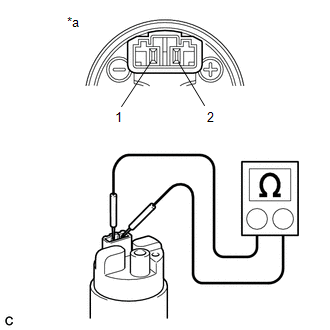
(a) Check the resistance.
| (1) Measure the resistance according to the value(s) in the table below. Standard Resistance:
If the result is not as specified, replace the fuel pump assembly with filter. |
|
(b) Operation check.
(1) Apply battery voltage between the terminals and check that the motor rotates.
NOTICE:
- Inspect for a short time (10 seconds or less).
- Keep the fuel pump assembly with filter as far away from the battery as possible.
- Be sure to always perform switching from the battery terminal.
- When the pump is locked and does not operate due to foreign matter being stuck, etc., replace the fuel pump control ECU assembly together with the fuel pump assembly with filter, as the fuel pump control ECU assembly may be damaged electrically.
If the fuel pump does not operate, replace the fuel pump assembly with filter.
READ NEXT:
 Reassembly
REASSEMBLY CAUTION / NOTICE / HINT NOTICE: Do not try to remove the black nylon tube as it is welded to the fuel suction tube assembly. Click here HINT: Perform "Inspection After Repairs" after rep
Installation
INSTALLATION CAUTION / NOTICE / HINT HINT: Perform "Inspection After Repairs" after replacing the fuel pump. Click here PROCEDURE 1. INSTALL FUEL SUCTION TUBE ASSEMBLY (a) Install a new gasket onto
Fuel Pump Ecu
ComponentsCOMPONENTS ILLUSTRATION *1 FUEL PUMP CONTROL ECU ASSEMBLY *2 PARKING BRAKE ECU ASSEMBLY N*m (kgf*cm, ft.*lbf): Specified torque - - RemovalREMOVAL PROCEDURE 1. REMO
SEE MORE:
Passenger Side Buckle Switch Circuit Malfunction (B1771)
DESCRIPTION The front passenger side buckle switch circuit consists of the occupant detection ECU and front seat inner belt assembly RH. DTC B1771 is stored when a malfunction is detected in the front passenger side buckle switch circuit. Troubleshoot DTC B1771 first when DTCs B1771 and B1795 are ou
Freeze Frame Data
FREEZE FRAME DATA DESCRIPTION (a) Whenever a road sign assist system DTC is stored, the forward recognition camera stores the current vehicle state (ECU and sensor information) as freeze frame data. CHECK FREEZE FRAME DATA (a) Connect the Techstream to the DLC3. (b) Turn the power switch on (IG). (c
© 2016-2026 Copyright www.lexunx.com
