Lexus NX: Parts Location
Lexus NX Service Manual / Steering / Steering Column / Power Tilt And Power Telescopic Steering Column System / Parts Location
PARTS LOCATION
ILLUSTRATION
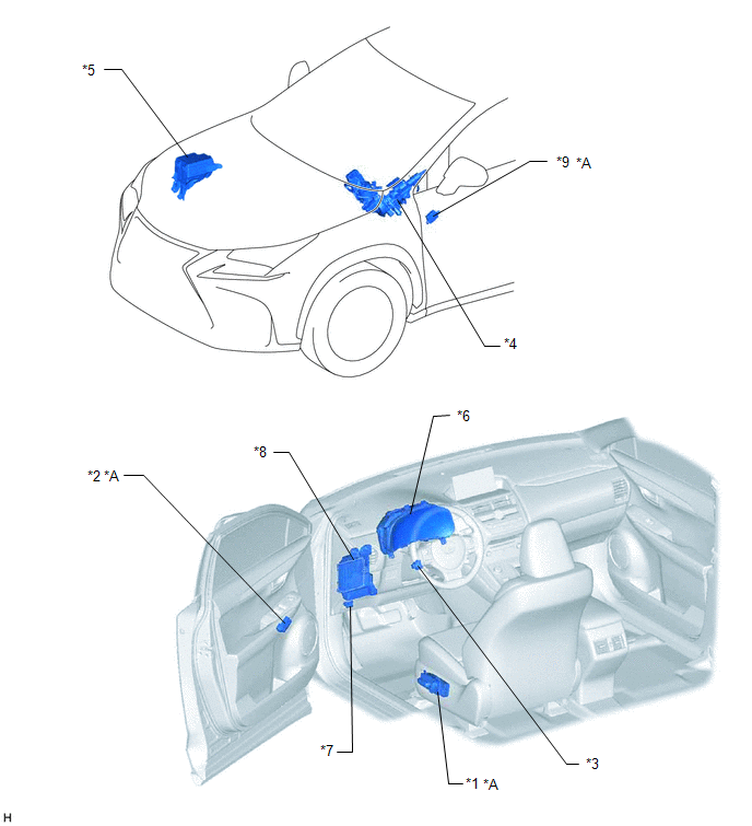
| *A | w/ Seat Memory | - | |
| *1 | FRONT POWER SEAT SWITCH LH | *2 | SEAT MEMORY SWITCH |
| *3 | TILT AND TELESCOPIC SWITCH | *4 | ELECTRIC POWER STEERING COLUMN SUB-ASSEMBLY - MULTIPLEX TILT AND TELESCOPIC ECU - TILT MOTOR - TELESCOPIC MOTOR |
| *5 | NO. 2 ENGINE ROOM RELAY BLOCK - ECU-B NO. 1 FUSE | *6 | COMBINATION METER ASSEMBLY |
| *7 | DLC3 | *8 | INSTRUMENT PANEL JUNCTION BLOCK ASSEMBLY - TI&TE FUSE - ECU-IG NO. 2 FUSE |
| *9 | OUTER MIRROR CONTROL ECU ASSEMBLY LH | - | - |
READ NEXT:
 System Description
SYSTEM DESCRIPTION FUNCTION OF MAIN COMPONENTS Component Function Multiplex tilt and telescopic ECU This ECU sends a control signal to the tilt motor and telescopic motor, based on signals
System Diagram
SYSTEM DIAGRAM Communication Table Transmitting ECU (Transmitter) Receiving ECU Signal Communication Method Main Body ECU (Multiplex Network Body ECU) Multiplex Tilt and Telescopic EC
How To Proceed With Troubleshooting
CAUTION / NOTICE / HINT HINT: *: Use the Techstream. PROCEDURE 1. VEHICLE BROUGHT TO WORKSHOP
NEXT 2. INSPECT AUXILIARY BATTERY VOLTAGE Standard voltage: 11 to 14 V
SEE MORE:
Removal
REMOVAL CAUTION / NOTICE / HINT CAUTION: Wear protective gloves. Sharp areas on the parts may injure your hands. PROCEDURE 1. REMOVE REAR SEAT ASSEMBLY Click here 2. REMOVE REAR SEATBACK COVER Click here 3. REMOVE REAR SEAT INNER WITH CENTER BELT ASSEMBLY RH (for RH Side) Click here 4. REMOVE
Components
COMPONENTS ILLUSTRATION *1 FRONT AXLE HUB BOLT LH *2 FRONT DISC *3 FRONT DISC BRAKE CALIPER ASSEMBLY LH - - N*m (kgf*cm, ft.*lbf): Specified torque ● Non-reusable part
© 2016-2026 Copyright www.lexunx.com
