Lexus NX: Inspection
INSPECTION
PROCEDURE
1. INSPECT STEERING PAD SWITCH ASSEMBLY
(a) Measure the resistance according to the value(s) in the table below.
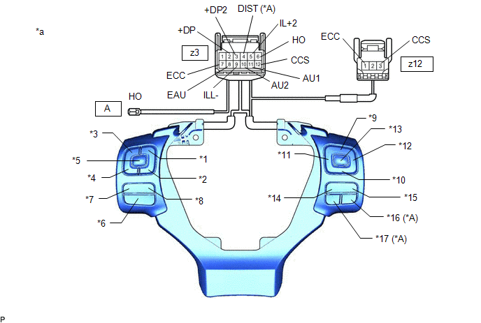
| *A | w/ Lane Departure Alert System | - | - |
| *1 | SEEK+ | *2 | SEEK- |
| *3 | VOL+ | *4 | VOL- |
| *5 | MODE | *6 | VOICE |
| *7 | OFF HOOK | *8 | ON HOOK |
| *9 | UP | *10 | DOWN |
| *11 | LEFT | *12 | RIGHT |
| *13 | ENTER | *14 | TOP |
| *15 | BACK | *16 | ACC |
| *17 | LDA | - | - |
| *a | Component without harness connected (Steering Pad Switch Assembly) | - | - |
Standard Resistance:
| Tester Connection | Condition | Specified Condition |
|---|---|---|
| z3-11 (AU1) - z3-8 (EAU) | No switch pushed | 95 to 105 kΩ |
| SEEK+ switch pushed | Below 2.5 Ω | |
| SEEK- switch pushed | 313 to 345 Ω | |
| Volume+ switch pushed | 950 to 1050 Ω | |
| Volume- switch pushed | 2955 to 3265 Ω | |
| z3-10 (AU2) - z3-8 (EAU) | No switch pushed | 95 to 105 kΩ |
| MODE switch pushed | Below 2.5 Ω | |
| On hook switch pushed | 313 to 345 Ω | |
| Off hook switch pushed | 950 to 1050 Ω | |
| Voice switch pushed | 2955 to 3265 Ω | |
| z3-3 (+DP2) - z3-8 (EAU) | No switch pushed | 95 to 105 kΩ |
| Left switch pushed | Below 2.5 Ω | |
| Up switch pushed | 313 to 345 Ω | |
| Down switch pushed | 950 to 1050 Ω | |
| Right switch pushed | 2955 to 3265 Ω | |
| z3-2 (+DP) - z3-8 (EAU) | No switch pushed | 95 to 105 kΩ |
| Enter switch pushed | Below 2.5 Ω | |
| Top switch pushed | 313 to 345 Ω | |
| Back switch pushed | 950 to 1050 Ω | |
| z3-4 (DIST)* - z3-7 (ECC) | No switch pushed | 1 MΩ or higher |
| Distance control switch pushed | Below 2.5 Ω | |
| Lane departure alert main switch pushed | 228 to 252 Ω | |
| z3-1 (HO) - A-1 (HO) | Always | Below 2.5 Ω |
| z3-7 (ECC) - z12-1 (ECC) | Always | Below 2.5 Ω |
| z3-12 (CCS) - z12-3 (CCS) | Always | Below 2.5 Ω |
- *: w/ Lane Departure Alert System
HINT:
If the result is not as specified, replace the steering pad switch assembly.
(b) Check the illumination.
(1) Connect a battery positive (+) lead to terminal z3-5 (IL+2) and a negative (-) lead to terminal z3-9 (ILL-) of the steering pad switch assembly connector.
(2) Check that the switch illumination comes on.
OK:
Steering pad switch illumination comes on.
HINT:
If the result is not as specified, replace the steering pad switch assembly.
READ NEXT:
 Installation
INSTALLATION PROCEDURE 1. INSTALL STEERING PAD SWITCH ASSEMBLY (a) Engage the 4 claws and 3 guide pins to install the steering pad switch assembly to the steering wheel sub-assembly. (b) Install the 2
Precaution
PRECAUTION HANDLING PRECAUTIONS FOR SRS AIRBAG SYSTEM Click here HANDLING PRECAUTIONS FOR STEERING COLUMN (a) When handling the electric power steering column sub-assembly: (1) Avoid any impact to
SEE MORE:
Components
COMPONENTS ILLUSTRATION *1 CENTER EXHAUST PIPE ASSEMBLY *2 EXHAUST PIPE DAMPER *3 FRONT EXHAUST PIPE ASSEMBLY *4 HEATED OXYGEN SENSOR *5 TAIL EXHAUST PIPE ASSEMBLY *6 EXHAUST PIPE SUPPORT *7 COMPRESSION SPRING *8 GASKET N*m (kgf*cm, ft.*lbf): Specified
Inspection
INSPECTION PROCEDURE 1. INSPECT FUEL PUMP ASSEMBLY WITH FILTER (a) Check the resistance. (1) Measure the resistance according to the value(s) in the table below. Standard Resistance: Tester Connection Condition Specified Condition 1 - 2 20°C (68°F) 0.2 to 3.0 Ω If the result
