Lexus NX: Parts Location
PARTS LOCATION
ILLUSTRATION
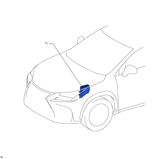
| *1 | NO. 1 ENGINE ROOM RELAY BLOCK - IG2-MAIN RELAY - IG2-MAIN FUSE - STRG LOCK FUSE | - | - |
ILLUSTRATION

| *1 | POWER SWITCH | *2 | INSTRUMENT PANEL JUNCTION BLOCK ASSEMBLY - IG2 NO. 3 FUSE |
| *3 | MAIN BODY ECU (MULTIPLEX NETWORK BODY ECU) | *4 | DLC3 |
| *5 | COMBINATION METER ASSEMBLY | *6 | STEERING LOCK ECU (STEERING LOCK ACTUATOR ASSEMBLY) (for Manual Tilt and Manual Telescopic Steering Column) |
| *7 | STEERING LOCK ECU (STEERING LOCK ACTUATOR ASSEMBLY) (for Power Tilt and Power Telescopic Steering Column) | *8 | CERTIFICATION ECU (SMART KEY ECU ASSEMBLY) |
| *9 | ID CODE BOX (IMMOBILISER CODE ECU) | - | - |
READ NEXT:
 System Diagram
SYSTEM DIAGRAM Circuit Description Component Outline Steering Lock ECU (Steering Lock Actuator Assembly)
The steering is locked and unlocked by communicating with the certification ECU
System Description
SYSTEM DESCRIPTION UNLOCK OPERATION CONDITIONS FOR STEERING LOCK (a) When the following condition is met, the unlock operation is performed.
The power switch is on (ACC) or on (IG).
HINT: When t
How To Proceed With Troubleshooting
CAUTION / NOTICE / HINT HINT:
Use the following procedures to troubleshoot the steering lock system.
*: Use the Techstream.
PROCEDURE 1. VEHICLE BROUGHT TO WORKSHOP
NEXT
SEE MORE:
On-vehicle Inspection
ON-VEHICLE INSPECTION CAUTION / NOTICE / HINT CAUTION: Be sure to follow the correct removal and installation procedures of the seat position airbag sensor. PROCEDURE 1. INSPECT SEAT POSITION AIRBAG SENSOR (for Vehicle not Involved in Collision) (a) Perform a diagnostic system check. Click here 2
Inspection
INSPECTION PROCEDURE 1. INSPECT OUTER MIRROR SWITCH ASSEMBLY (w/ Memory) (a) Check the mirror retract switch. (1) Measure the resistance according to the value(s) in the table below. Standard Resistance: Tester Connection Condition Specified Condition 8 (MR) - 10 (E) Driving positio
© 2016-2026 Copyright www.lexunx.com
