Lexus NX: Parts Location
PARTS LOCATION
ILLUSTRATION
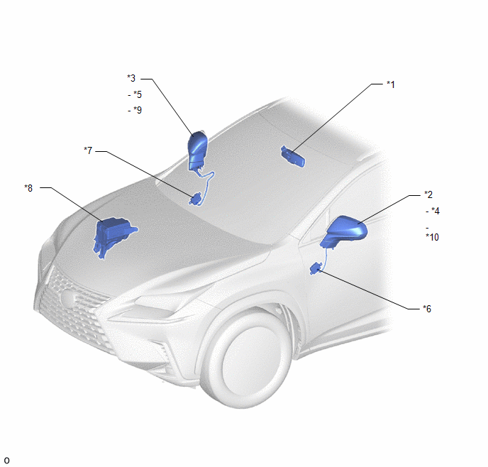
| *1 | INNER REAR VIEW MIRROR ASSEMBLY | *2 | OUTER REAR VIEW MIRROR ASSEMBLY LH |
| *3 | OUTER REAR VIEW MIRROR ASSEMBLY RH | *4 | OUTER MIRROR LH |
| *5 | OUTER MIRROR RH | *6 | OUTER MIRROR CONTROL ECU ASSEMBLY LH |
| *7 | OUTER MIRROR CONTROL ECU ASSEMBLY RH | *8 | NO. 2 ENGINE ROOM RELAY BLOCK - MIRROR FUSE - ECU-B NO.1 FUSE |
| *9 | OUTER MIRROR RETRACTOR RH | *10 | OUTER MIRROR RETRACTOR LH |
ILLUSTRATION
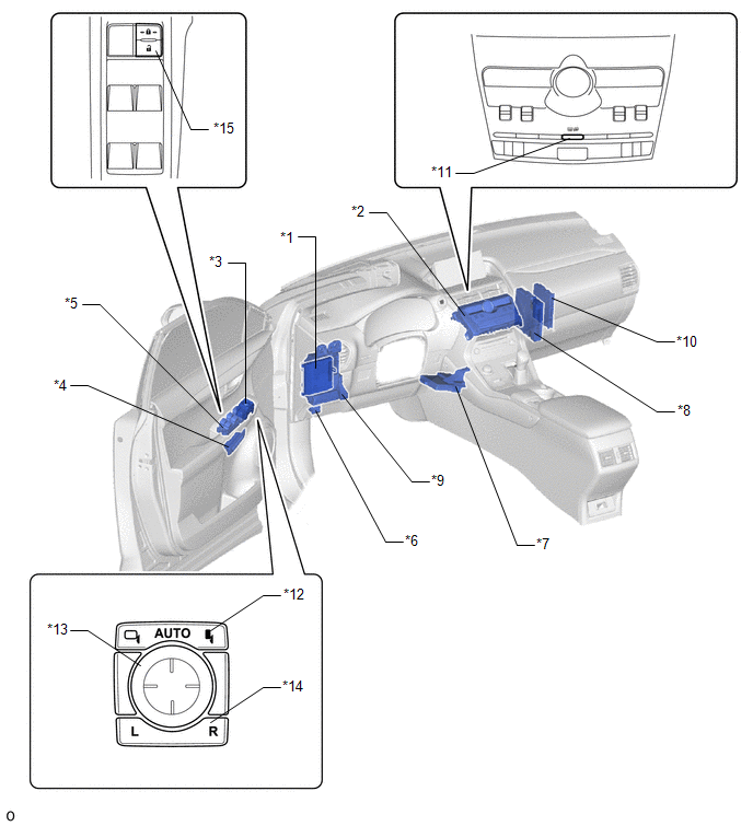
| *1 | MAIN BODY ECU (MULTIPLEX NETWORK BODY ECU) | *2 | AIR CONDITIONING CONTROL ASSEMBLY |
| *3 | OUTER MIRROR SWITCH ASSEMBLY | *4 | SEAT MEMORY SWITCH |
| *5 | MULTIPLEX NETWORK MASTER SWITCH ASSEMBLY | *6 | DLC3 |
| *7 | AIR CONDITIONING AMPLIFIER ASSEMBLY | *8 | HYBRID VEHICLE CONTROL ECU |
| *9 | INSTRUMENT PANEL JUNCTION BLOCK ASSEMBLY - ECU-IG NO.1 FUSE - ECU-IG NO.2 FUSE | *10 | CERTIFICATION ECU (SMART KEY ECU ASSEMBLY) |
| *11 | REAR WINDOW DEFOGGER SWITCH | *12 | MIRROR RETRACT SWITCH |
| *13 | MIRROR SURFACE ADJUST SWITCH | *14 | MIRROR SELECT SWITCH |
| *15 | DOOR CONTROL SWITCH | - | - |
READ NEXT:
 System Diagram
SYSTEM DIAGRAM Communication Table Sender Receiver Signal Line Main body ECU (multiplex network body ECU) Outer mirror control ECU assembly LH and RH
Mirror surface adjust swi
System Description
SYSTEM DESCRIPTION POWER MIRROR CONTROL SYSTEM DESCRIPTION (a) This system has the following functions: power retract function, auto power retract function, electrical remote control function, reverse
How To Proceed With Troubleshooting
CAUTION / NOTICE / HINT HINT:
Use the following procedures to troubleshoot the power mirror control system.
*: Use the Techstream.
PROCEDURE 1. VEHICLE BROUGHT TO WORKSHOP
NEXT
SEE MORE:
System Description
SYSTEM DESCRIPTION WIRELESS DOOR LOCK CONTROL SYSTEM The wireless door lock control system can be used to lock and unlock all doors from a distance. The system is controlled by an electrical key transmitter sub-assembly which sends radio waves to the door control receiver. The certification ECU (sma
Internal Control Module Software Incompatibility Not Programmed (U030051,U030057)
DESCRIPTION
The forward recognition camera receives vehicle information from the hybrid vehicle control ECU via the CAN communication line.
When the forward recognition camera is unable to determine the vehicle information from the vehicle information sent from the hybrid vehicle control ECU, t
