Lexus NX: Parts Location
PARTS LOCATION
ILLUSTRATION
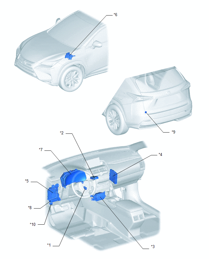
| *1 | VEHICLE SOUND SWITCH | *2 | STEREO COMPONENT EQUALIZER ASSEMBLY |
| *3 | NO. 1 SPEAKER ASSEMBLY WITH BOX | *4 | HYBRID VEHICLE CONTROL ECU |
| *5 | MAIN BODY ECU (MULTIPLEX NETWORK BODY ECU) | *6 | BRAKE BOOSTER WITH MASTER CYLINDER ASSEMBLY - SKID CONTROL ECU |
| *7 | COMBINATION METER ASSEMBLY | *8 | INSTRUMENT PANEL JUNCTION BLOCK ASSEMBLY - ECU-IG NO.2 FUSE - PANEL FUSE |
| *9 | FUSE BLOCK - ECU-B NO.3 FUSE | *10 | DLC3 |
READ NEXT:
 System Diagram
SYSTEM DIAGRAM Communication Table Sender Receiver Signal Line Brake booster with master cylinder assembly (skid control ECU) Stereo component equalizer assembly Vehicle speed signal
System Description
SYSTEM DESCRIPTION ASC SYSTEM (a) The ASC system uses a stereo component equalizer assembly to electronically generate a driving sound. Simulated engine sounds are output from the No. 1 speaker assemb
How To Proceed With Troubleshooting
CAUTION / NOTICE / HINT HINT:
Use the following procedure to troubleshoot the ASC system.
*: Use the Techstream.
PROCEDURE 1. VEHICLE BROUGHT TO WORKSHOP
NEXT 2.
SEE MORE:
ECU Malfunction (C1611)
DESCRIPTION This DTC is stored if the rear television camera assembly judges that there is an internal malfunction as a result of its self check. HINT: The rear television camera assembly stores different types of information during initialization. If the rear television camera assembly cannot read
Removal
REMOVAL CAUTION / NOTICE / HINT NOTICE: When replacing the windshield glass of a vehicle equipped with a forward recognition camera, make sure to use a Lexus genuine part. If a non-Lexus genuine part is used, the forward recognition camera may not be able to be installed due to a missing bracket. Al
© 2016-2026 Copyright www.lexunx.com
