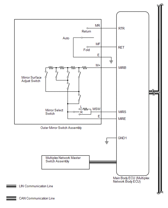
- Mirror surface adjust switch signal
- Mirror select switch signal
- Mirror retract switch signal
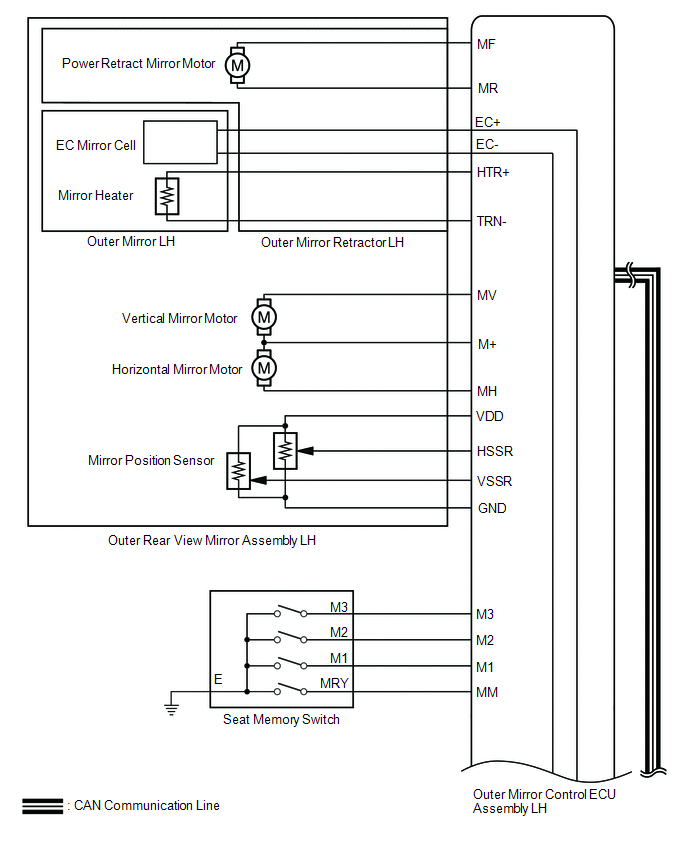
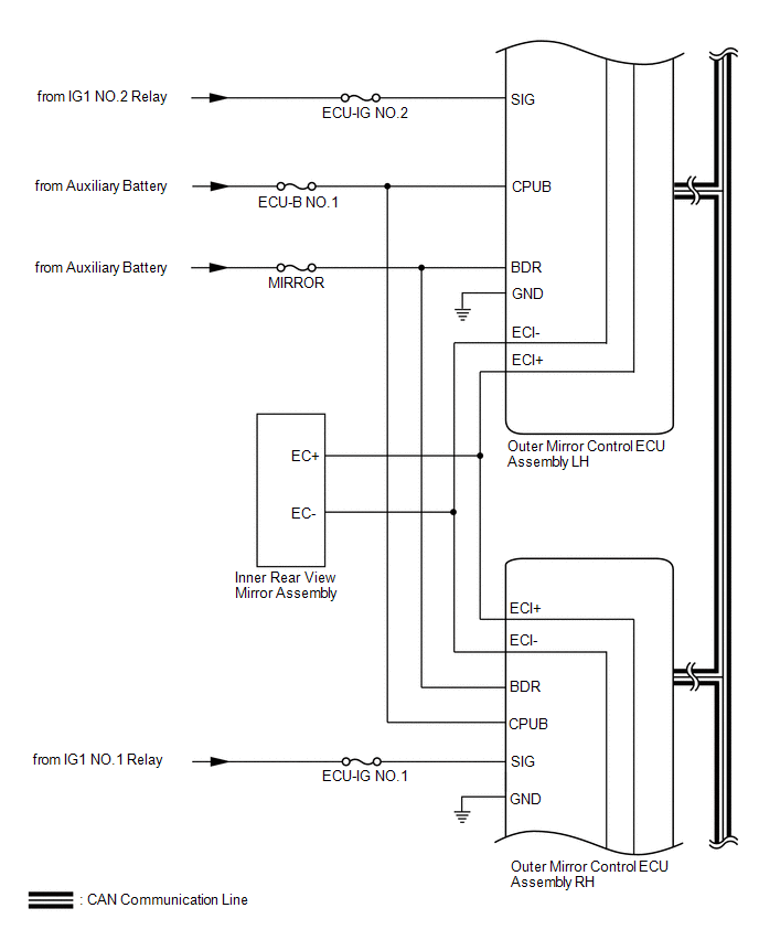
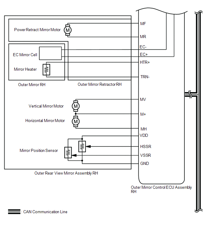
Lexus NX: System Diagram
Lexus NX Service Manual / Vehicle Exterior / Mirror (ext) / Power Mirror Control System (w/ Memory) / System Diagram
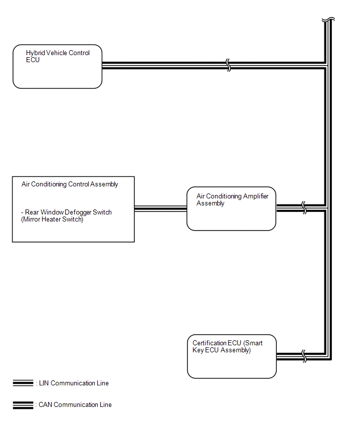
SYSTEM DIAGRAM
 Communication Table
 | Sender | Receiver | Signal | Line |
|---|---|---|---|
| Main body ECU (multiplex network body ECU) | Outer mirror control ECU assembly LH and RH | | CAN |
| Mirror position request signal / memory request signal, reverse memory request signal, memory call request signal, reverse request signal or return request signal | |||
| Power switch signal | |||
| Outer mirror control ECU assembly LH | Main body ECU (multiplex network body ECU) |
| |
| Outer mirror control ECU assembly LH and RH | Outer mirror state signal / manual operation, memory operation, reverse operation or return operation | ||
| Hybrid vehicle control ECU | Reverse signal | ||
| Air conditioning amplifier assembly | Outer mirror control ECU assembly LH and RH | Mirror heater operation request signal | |
| Air conditioning control assembly | Air conditioning amplifier assembly | Mirror heater operation request signal | LIN |
READ NEXT:
 System Description
SYSTEM DESCRIPTION POWER MIRROR CONTROL SYSTEM DESCRIPTION (a) This system has the following functions: power retract function, auto power retract function, electrical remote control function, reverse
How To Proceed With Troubleshooting
CAUTION / NOTICE / HINT HINT:
Use the following procedures to troubleshoot the power mirror control system.
*: Use the Techstream.
PROCEDURE 1. VEHICLE BROUGHT TO WORKSHOP
NEXT
Operation Check
OPERATION CHECK CHECK OUTER MIRROR SWITCH FUNCTION (a) Turn the power switch on (ACC). (b) With the mirror select switch set to L, check that the mirror surface moves up, down, left and right normally
SEE MORE:
Diagnosis System
DIAGNOSIS SYSTEM CHECK DLC3 (a) Check the DLC3. Click here INSPECT AUXILIARY BATTERY VOLTAGE (a) Measure the auxiliary battery voltage with the power switch off. Standard voltage: 11 to 14 V If the voltage is below 11 V, recharge or replace the auxiliary battery.
Installation
INSTALLATION PROCEDURE 1. INSTALL BLOWER ASSEMBLY (a) Attach the 2 claws to install the blower assembly. (b) Install the 2 screws. (c) Attach the 3 clamps to install the air conditioning harness assembly. (d) Connect the No. 1 blower damper servo sub-assembly connector. 2. INSTALL AIR CONDITIONING U
© 2016-2026 Copyright www.lexunx.com
