Lexus NX: Parts Location
PARTS LOCATION
ILLUSTRATION
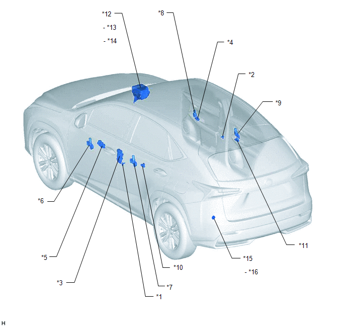
| *1 | FRONT DOOR COURTESY LIGHT SWITCH ASSEMBLY LH | *2 | FRONT DOOR COURTESY LIGHT SWITCH ASSEMBLY RH |
| *3 | FRONT DOOR LOCK ASSEMBLY LH | *4 | POWER WINDOW REGULATOR SWITCH ASSEMBLY |
| *5 | MULTIPLEX NETWORK MASTER SWITCH ASSEMBLY | *6 | FRONT POWER WINDOW REGULATOR MOTOR ASSEMBLY LH |
| *7 | REAR POWER WINDOW REGULATOR MOTOR ASSEMBLY LH | *8 | FRONT POWER WINDOW REGULATOR MOTOR ASSEMBLY RH |
| *9 | REAR POWER WINDOW REGULATOR MOTOR ASSEMBLY RH | *10 | REAR POWER WINDOW REGULATOR SWITCH ASSEMBLY (for Rear LH Door) |
| *11 | REAR POWER WINDOW REGULATOR SWITCH ASSEMBLY (for Rear RH Door) | *12 | NO. 2 ENGINE ROOM RELAY BLOCK |
| *13 | DOOR R/R FUSE | *14 | ECU-B NO.2 FUSE |
| *15 | FUSE BLOCK | *16 | ECU-B NO.3 FUSE |
ILLUSTRATION
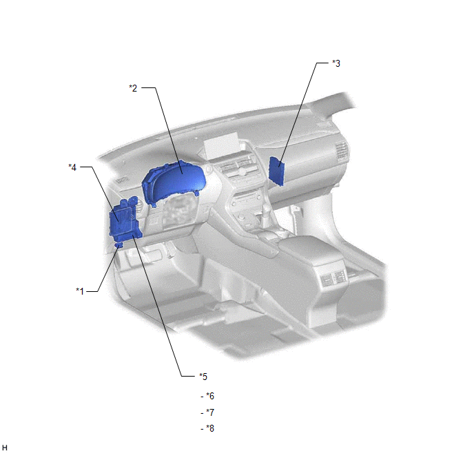
| *1 | DLC3 | *2 | COMBINATION METER ASSEMBLY |
| *3 | CERTIFICATION ECU (SMART KEY ECU ASSEMBLY) | *4 | MAIN BODY ECU (MULTIPLEX NETWORK BODY ECU) |
| *5 | INSTRUMENT PANEL JUNCTION BLOCK ASSEMBLY | *6 | DOOR F/R FUSE |
| *7 | DOOR F/L FUSE | *8 | DOOR R/L FUSE |
READ NEXT:
 System Diagram
SYSTEM DIAGRAM Communication Table Transmitting ECU Receiving ECU Signal Communication Method Multiplex Network Master Switch Assembly Front Power Window Regulator Motor Assembly LH
System Description
SYSTEM DESCRIPTION POWER WINDOW CONTROL SYSTEM DESCRIPTION (a) The power window control system controls the power window operation using the power window regulator motors. The main controls of this sy
How To Proceed With Troubleshooting
CAUTION / NOTICE / HINT HINT:
Use the following procedure to troubleshoot the power window control system.
*: Use the Techstream.
PROCEDURE 1. VEHICLE BROUGHT TO WORKSHOP
NEXT
SEE MORE:
Installation
INSTALLATION PROCEDURE 1. INSTALL TRIP SWITCH (a) Attach the 2 claws to install the trip switch. 2. INSTALL NO. 1 INSTRUMENT PANEL SAFETY PAD SUB-ASSEMBLY Click here 3. INSTALL INSTRUMENT SIDE PANEL LH Click here
Components
COMPONENTS ILLUSTRATION *A w/ Power Back Door *B w/o Power Back Door *1 BACK DOOR CENTER GARNISH *2 BACK DOOR FINISH COVER LH *3 BACK DOOR FINISH COVER RH *4 BACK DOOR LOCK COVER *5 BACK DOOR SIDE GARNISH LH *6 BACK DOOR SIDE GARNISH RH *7 BACK DOOR TRIM
