- Front Power Window Regulator Motor Assembly RH
- Rear Power Window Regulator Motor Assembly LH
- Rear Power Window Regulator Motor Assembly RH
Lexus NX: System Diagram
Lexus NX Service Manual / Vehicle Exterior / Window / Glass / Power Window Control System / System Diagram
SYSTEM DIAGRAM
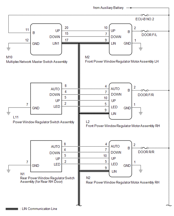
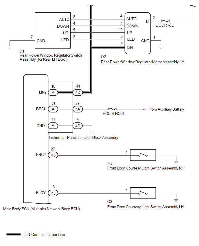
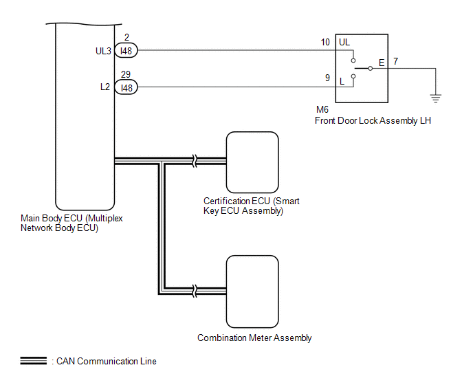 Communication Table
 | Transmitting ECU | Receiving ECU | Signal | Communication Method |
|---|---|---|---|
| Multiplex Network Master Switch Assembly | Front Power Window Regulator Motor Assembly LH | Power window auto up and down signal | LIN |
| | Power window remote up and down signal | LIN | |
| Main Body ECU (Multiplex Network Body ECU) |
| Power window operation permission signal | LIN |
| Certification ECU (Smart Key ECU Assembly) | Main Body ECU (Multiplex Network Body ECU) | Wireless power window operation signal | CAN |
| Main Body ECU (Multiplex Network Body ECU) | Combination Meter Assembly | Window open warning request signal | CAN |
READ NEXT:
 System Description
SYSTEM DESCRIPTION POWER WINDOW CONTROL SYSTEM DESCRIPTION (a) The power window control system controls the power window operation using the power window regulator motors. The main controls of this sy
How To Proceed With Troubleshooting
CAUTION / NOTICE / HINT HINT:
Use the following procedure to troubleshoot the power window control system.
*: Use the Techstream.
PROCEDURE 1. VEHICLE BROUGHT TO WORKSHOP
NEXT
Operation Check
OPERATION CHECK CHECK WINDOW LOCK FUNCTION (a) Turn the power switch on (IG). (b) Press the window lock switch of the multiplex network master switch assembly. HINT: The illumination (LED) built into
SEE MORE:
Short in D Squib (Dual Stage - 2nd Step) Circuit (B1810-B1813)
DESCRIPTION The driver side squib 2nd step circuit consists of the airbag ECU assembly, spiral cable sub-assembly and horn button assembly. The circuit instructs the SRS to deploy when deployment conditions are met. These DTCs are stored when a malfunction is detected in the driver side squib 2nd st
Lost Communication with Drive Motor Control Module "A" (U0110-160)
DESCRIPTION The MG ECU, which is built into in the inverter with converter assembly, controls motor (MG2) based on commands from the hybrid vehicle control ECU. The motor generator control ECU (MG ECU) monitors communication data and detects malfunctions. A communication error between the MG ECU and
© 2016-2026 Copyright www.lexunx.com
