Lexus NX: Parts Location
PARTS LOCATION
ILLUSTRATION
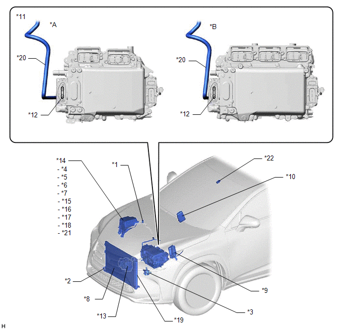
| *A | for 2WD | *B | for AWD |
| *1 | AIR CONDITIONING TUBE AND ACCESSORY ASSEMBLY (AIR CONDITIONER PRESSURE SENSOR) | *2 | THERMISTOR ASSEMBLY (AMBIENT TEMPERATURE SENSOR) |
| *3 | HEATER ACCESSORY ASSEMBLY | *4 | PTC HTR NO.1 RELAY |
| *5 | PTC HTR NO.2 RELAY | *6 | PTC HTR NO.3 RELAY |
| *7 | A/C W/PMP RELAY | *8 | COOLER CONDENSER ASSEMBLY |
| *9 | ECM | *10 | POWER STEERING ECU ASSEMBLY |
| *11 | INVERTER WITH CONVERTER ASSEMBLY | *12 | HIGH VOLTAGE FUSE |
| *13 | COMPRESSOR WITH MOTOR ASSEMBLY | *14 | NO. 2 ENGINE ROOM RELAY BLOCK |
| *15 | HTR FUSE | *16 | PTC HTR NO.1 FUSE |
| *17 | PTC HTR NO.2 FUSE | *18 | PTC HTR NO.3 FUSE |
| *19 | COOLER DRYER | *20 | ENGINE WIRE |
| *21 | ECU-B NO.2 FUSE | *22 | AIR CONDITIONING THERMISTOR ASSEMBLY |
ILLUSTRATION
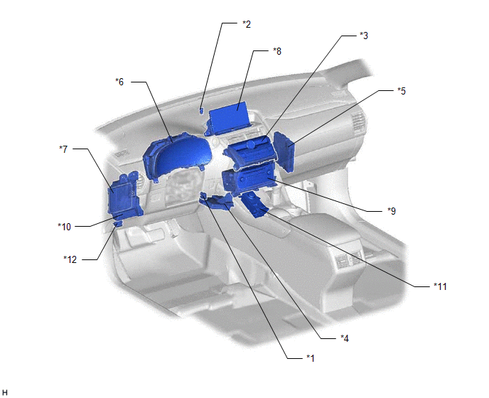
| *1 | COOLER THERMISTOR (ROOM TEMPERATURE SENSOR) | *2 | AUTOMATIC LIGHT CONTROL SENSOR |
| *3 | AIR CONDITIONING CONTROL ASSEMBLY | *4 | AIR CONDITIONING AMPLIFIER ASSEMBLY |
| *5 | HYBRID VEHICLE CONTROL ECU | *6 | COMBINATION METER ASSEMBLY |
| *7 | MAIN BODY ECU (MULTIPLEX NETWORK BODY ECU) | *8 | MULTI-DISPLAY ASSEMBLY |
| *9 | RADIO RECEIVER ASSEMBLY | *10 | INSTRUMENT PANEL JUNCTION BLOCK ASSEMBLY - ECU-IG NO.1 FUSE - ECU-IG NO.2 FUSE - ECU-IG NO.3 FUSE |
| *11 | INTEGRATION CONTROL AND PANEL ASSEMBLY | *12 | DLC3 |
ILLUSTRATION
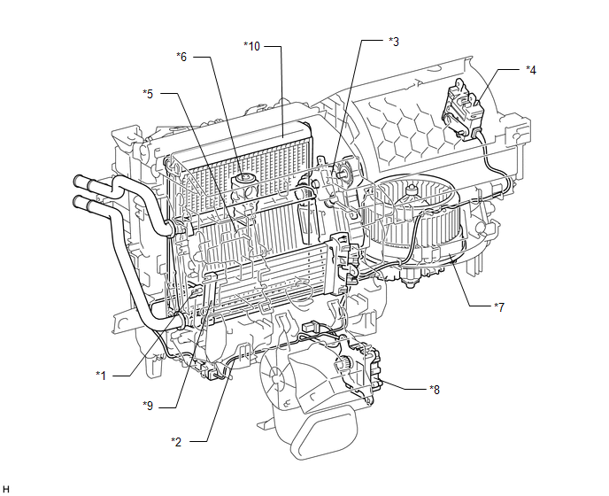
| *1 | NO. 1 COOLER THERMISTOR (EVAPORATOR TEMPERATURE SENSOR) | *2 | AIR CONDITIONING HARNESS ASSEMBLY |
| *3 | NO. 1 AIR CONDITIONING RADIATOR DAMPER SERVO SUB-ASSEMBLY | *4 | NO. 1 BLOWER MODE DAMPER SERVO SUB-ASSEMBLY |
| *5 | HEATER RADIATOR UNIT SUB-ASSEMBLY | *6 | COOLER EXPANSION VALVE |
| *7 | BLOWER WITH FAN MOTOR SUB-ASSEMBLY | *8 | NO. 2 AIR CONDITIONING RADIAOTR DAMPER SERVO SUB-ASSEMBLY |
| *9 | QUICK HEATER ASSEMBLY | *10 | NO. 1 COOLER EVAPORATOR SUB-ASSEMBLY |
READ NEXT:
 System Diagram
SYSTEM DIAGRAM Communication Table Sender Receiver Signal Communication Line Air conditioning amplifier assembly Hybrid vehicle control ECU Heater idle up request signal CAN
System Description
SYSTEM DESCRIPTION GENERAL (a) The air conditioning system has the following controls. Control Outline Neural Network Control This control is capable of performing complex control by artifi
How To Proceed With Troubleshooting
CAUTION / NOTICE / HINT HINT:
Use the following procedure to troubleshoot the air conditioning system.
*: Use the Techstream.
PROCEDURE 1. VEHICLE BROUGHT TO WORKSHOP
NEXT
SEE MORE:
Vehicle Control History
VEHICLE CONTROL HISTORY NOTICE: When checking the vehicle control history, first record the output codes and after clearing the history, check the output history again. CHECK VEHICLE CONTROL HISTORY (LANE TRACING ASSIST SYSTEM) (a) Connect the Techstream to the DLC3. (b) Turn the power switch on (IG
Side Camera RH Internal Circuit (C2A62)
DESCRIPTION This DTC is stored when the parking assist ECU detects a signal indicating a malfunction in the side television camera assembly RH via CAN communication. DTC No. Detection Item DTC Detection Condition Trouble Area C2A62 Side Camera RH Internal Circuit A signal indicating
