- Engine coolant temperature is below specified temperature.
- Outside temperature is below specified temperature.
- Tentative air mix damper opening angle is above the specified value (MAX HOT).
Lexus NX: System Description
Lexus NX Service Manual / Vehicle Interior / Heating / Air Conditioning / Air Conditioning System / System Description
SYSTEM DESCRIPTION
GENERAL
(a) The air conditioning system has the following controls.
| Control | Outline |
|---|---|
| Neural Network Control | This control is capable of performing complex control by artificially simulating the information processing method of the nervous system of living organisms in order to establish a complex input/output relationship similar to that of a human brain. |
| Outlet Air Temperature Control | Based on the temperature set by the temperature control dial, neural network control calculates outlet air temperature based on input signals from various sensors. |
| Dual Control | The temperature settings for the driver and front passenger are controlled independently in order to provide separate vehicle interior temperatures for the right and left sides of the vehicle. Thus, the air conditioning accommodates the occupants' preferences. |
| Blower Control | Controls the blower motor in accordance with the airflow volume that has been calculated by neural network control based on the input signals from various sensors. |
| Air Outlet Control | Automatically switches the air outlets in accordance with the outlet mode that has been calculated by neural network control. |
| In accordance with the engine coolant temperature, ambient air temperature, amount of sunlight, required blower, outlet temperature and vehicle speed conditions, this control automatically switches the blower outlet to foot and defroster mode to prevent the windows from becoming fogged up when the ambient air temperature is low. | |
| Air Inlet Control | Automatically controls the air inlet control damper to help achieve the calculated outlet air temperature that is required. |
| Drives the air inlet control servo motor according to the operation of the air inlet control switch and moves the dampers to the fresh or recirculation position. | |
| Electric Inverter Compressor Control | Through the calculation of the target evaporator temperature based on various sensor signals, the air conditioning amplifier optimally controls discharge capacity by regulating the opening extent of the compressor solenoid valve. The air conditioning amplifier assembly calculates the target speed of the compressor based on the target evaporator temperature (which is calculated by the cooler (room temperature sensor) thermistor, thermistor assembly, automatic light control sensor) and the actual evaporator temperature that is detected by the No. 1 cooler thermistor in order to control the compressor speed. |
| The air conditioning amplifier assembly calculates the target evaporator temperature, which includes corrections based on the cooler (room temperature sensor) thermistor, thermistor assembly, the automatic light control sensor, and No. 1 cooler thermistor. Accordingly, the air conditioning amplifier assembly controls the compressor speed to an extent that would not inhibit the proper cooling performance or defogging performance. | |
| Turns the air conditioning on automatically when the AUTO button is pressed when the air conditioning is off. | |
| Decreases the compressor speed in order to ensure quietness when the vehicle is stopped or the engine is off. | |
| Defroster Control | Defroster control logic is used to improve defroster performance. |
| PTC Heater Control | When the hybrid control system is operating (READY), and the blower motor with fan sub-assembly is turned on, the air conditioning amplifier assembly turns on the quick heater assembly if the conditions listed below are met. |
| ECO Mode Control | When the integration control and panel assembly (ECO mode switch) is turned on, the air conditioning amplifier assembly limits the air conditioning system performance. |
| Diagnosis | A Diagnostic Trouble Code (DTC) is stored in memory when the air conditioning amplifier detects a problem with the air conditioning system. |
MODE POSITION AND DAMPER OPERATION
(a) Mode Position and Damper Operation
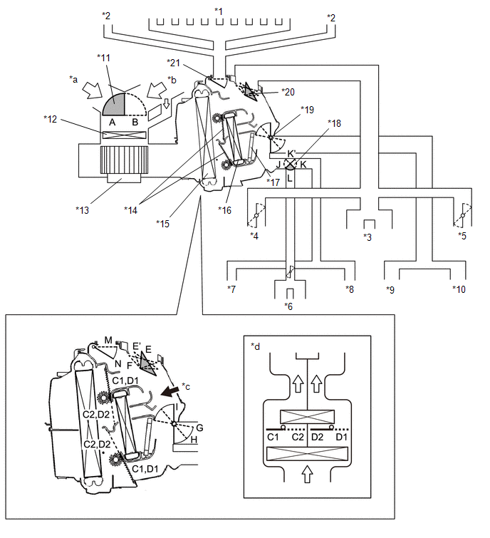
| *1 | Front Defroster | *2 | Side Defroster |
| *3 | Center Register | *4 | Driver Side Side Register |
| *5 | Front Passenger Side Side Register | *6 | Console Rear Face Register |
| *7 | Driver Side Rear Footwell Register | *8 | Front Passenger Side Rear Footwell Register |
| *9 | Driver Side Footwell Register | *10 | Front Passenger Side Footwell Register |
| *11 | Air Inlet Control Door | *12 | Clean Air Filter (Air Refiner Element) |
| *13 | Blower Motor with Fan Sub-assembly | *14 | Air Mix Control Door |
| *15 | No. 1 Cooler Evaporator Sub-assembly | *16 | Air Conditioning Radiator Sub-assembly |
| *17 | Quick Heater Assembly | *18 | Mode Control Door (for Rear Console Register) |
| *19 | Mode Control Door (for Front Footwell Register Duct) | *20 | Mode Control Door (for Front and Side Register) |
| *21 | Mode Control Door (for Front and Side Defroster) | - | - |
| *a | Fresh Air | *b | Recirculated Air |
| *c | [A] View | *d | Illustration Image View from [A] |
| Control Door | Operation Position | Door Position | Operation |
|---|---|---|---|
| Air Inlet Control Door | FRESH | B | Brings in fresh air. |
| RECIRCULATION | A | Recirculates internal air. | |
| Air Mix Control Door | HI - LO | C1 - C2 | Varies the driver side mixture ratio of the hot air and the cool air in order to regulate the temperature continuously from HI to LO. |
| D1 - D2 | Varies the front passenger side mixture ratio of the hot air and the cool air in order to regulate the temperature continuously from HI to LO. | ||
| Mode Control Door (for All Seat Control Mode) | FACE | E, I, K, M | Air blows out of the front center register, side register and console rear face register. |
| BI-LEVEL | E', H, K', M | Air blows out of the front center register, side register, console rear face register and front and rear footwell register ducts. | |
| FOOT | F, G, L, N | Air blows out of the front footwell register, rear footwell register and front register ducts. In addition, air blows out slightly from the front defroster, side defroster and console rear face register. | |
| FOOT/DEF | F, H, L, N | Defrosts the windshield through the front defroster. At the same time, air is blown out from the footwell register and rear footwell register. A small amount of air also blows out from the side register and console rear face register. | |
| DEF | F, I, J, N | Defrosts the windshield through the front defroster and side defroster. A small amount of air also blows out from the side register. | |
| Mode Control Door (for Front Seat Control Mode) | FACE | E, I, J, M | Air blows out of the front center register and side register. |
| BI-LEVEL | E', H, J, M | Air blows out of the front center register, side register and front footwell register ducts. | |
| FOOT | F, G, J, N | Air blows out of the front footwell register and front side register ducts. In addition, air blows out slightly from the front defroster and side defroster. | |
| FOOT/DEF | F, H, J, N | Defrosts the windshield through the front defroster. At the same time, air is blown out from the front footwell register. A small amount of air also blows out from the side register. |
AIR OUTLETS AND AIRFLOW VOLUME
(a) Air Outlets and Airflow Volume (for All Seat Control Modes)
| The size of each circle ○ indicates the ratio of air flow volume. | |||||||
| Mode | A | B | C | D | E | F | |
| Center Register | Side Register | Footwell Register | Defroster | Console Box Register | Rear Heater Duct | ||
 | FACE |  | | - | - | | - |
 | BI-LEVEL |  | | | - | | |
 | FOOT | - |  | | | | |
 | FOOT/DEF | - | | | | | |
 | DEF | - | | - | | - | - |
(b) Air Outlets and Air flow Volume (for Front Seat Control Modes)
| The size of each circle ○ indicates the ratio of air flow volume. | |||||||
| Mode | A | B | C | D | E | F | |
| Center Register | Side Register | Footwell Register | Defroster | Console Box Register | Rear Heater Duct | ||
| | FACE | | | - | - | - | - |
| | BI-LEVEL | | | | - | - | - |
| | FOOT | - | | | | - | - |
| | FOOT/DEF | - | | | | - | - |
AIR CONDITIONING FUNCTION
(a) After remote engine start and stop function operates, the air conditioning system operates according to the ambient temperature and customize settings.
| Ambient Temperature | Air Conditioning Control | Defroster/Rear Defogger Control |
|---|---|---|
|
*1: The set temperature can be changed using the application. (w/ Lexus Enform Remote)
*2: If the A/C switch was off when the power switch was turned off, the air conditioning system will automatically operate at a set temperature of 25°C (77°F). | ||
| 4°C (39.2°F) or less | Set temperature when power switch turned off*1, *2 | ON |
| Between 5°C (41°F) and 29°C (84.2°F) | Set temperature when power switch turned off*1 | OFF |
| 30°C (86°F) or more | Set temperature when power switch turned off*1, *2 | OFF |
READ NEXT:
 How To Proceed With Troubleshooting
CAUTION / NOTICE / HINT HINT:
Use the following procedure to troubleshoot the air conditioning system.
*: Use the Techstream.
PROCEDURE 1. VEHICLE BROUGHT TO WORKSHOP
NEXT
Customize Parameters
CUSTOMIZE PARAMETERS 1. CUSTOMIZE AIR CONDITIONING SYSTEM (a) Customizing with the Techstream HINT: The following items can be customized. NOTICE:
When the customer requests a change in a function,
Initialization
INITIALIZATION INITIALIZATION SERVO MOTOR (a) Turn the power switch off. (b) Connect the Techstream to the DLC3. (c) Turn the power switch on (IG). (d) Press the A/C OFF switch. (e) Turn the Techstrea
SEE MORE:
Removal
REMOVAL PROCEDURE 1. REMOVE NO. 3 DECK BOARD SUB-ASSEMBLY Click here 2. REMOVE REAR DECK FLOOR BOX Click here 3. REMOVE DECK FLOOR BOX LH Click here 4. PRECAUTION CAUTION: Be sure to read Precoution thoroughly before serving. Click here NOTICE: After turning the power switch off, there may b
Inspection
INSPECTION PROCEDURE 1. INSPECT QUICK HEATER ASSEMBLY (a) Measure the resistance according to the value(s) in the table below. Standard Resistance: Tester Connection Condition Specified Condition A-1 (B) - B-1 (E) Always Below 1 Ω A-2 (E) - B-2 (B) Always Below 1 Ω A
© 2016-2026 Copyright www.lexunx.com
