- - S/HTR F/L FUSE
- - ECU-IG NO.1 FUSE
Lexus NX: Parts Location
PARTS LOCATION
ILLUSTRATION
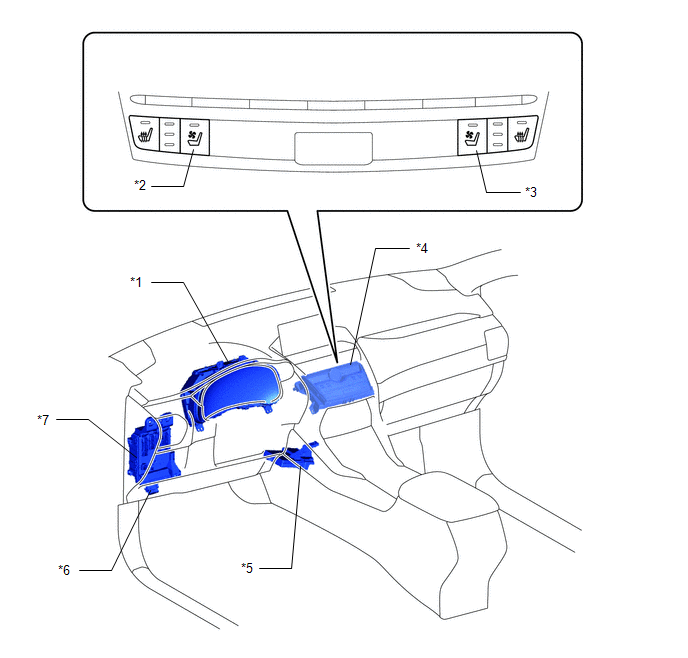
| *1 | COMBINATION METER ASSEMBLY | *2 | CLIMATE CONTROL SWITCH (for Driver Side) |
| *3 | CLIMATE CONTROL SWITCH (for Front Passenger Side) | *4 | AIR CONDITIONING CONTROL ASSEMBLY |
| *5 | AIR CONDITIONING AMPLIFIER ASSEMBLY | *6 | DLC3 |
| *7 | INSTRUMENT PANEL JUNCTION BLOCK ASSEMBLY | - | - |
ILLUSTRATION
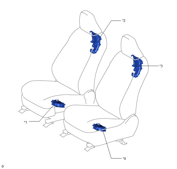
| *1 | SEAT CUSHION CLIMATE CONTROL BLOWER ASSEMBLY RH | *2 | SEATBACK CLIMATE CONTROL BLOWER RH |
| *3 | SEATBACK CLIMATE CONTROL BLOWER LH | *4 | SEAT CUSHION CLIMATE CONTROL BLOWER ASSEMBLY LH |
ILLUSTRATION
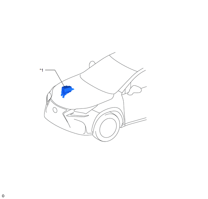
| *1 | NO. 2 ENGINE ROOM RELAY BLOCK
| - | - |
READ NEXT:
 System Diagram
SYSTEM DIAGRAM
System Description
SYSTEM DESCRIPTION GENERAL (a) The seat blower has 3 levels, controlled by operating the climate control switch on air conditioning control assembly. (b) Whether the blower is on or off can be determi
How To Proceed With Troubleshooting
CAUTION / NOTICE / HINT HINT:
Use this procedure to troubleshoot the climate control seat system.
*: Use the Techstream.
PROCEDURE 1. VEHICLE BROUGHT TO WORKSHOP
NEXT
SEE MORE:
Data List / Active Test
DATA LIST / ACTIVE TEST NOTICE:
In the table below, the values listed under "Normal Condition" are reference values. Do not depend solely on these reference values when deciding whether a part is faulty or not.
When diagnosing symptoms such as hesitation, rough idle, or other small symptoms usi
Removal
REMOVAL PROCEDURE 1. REMOVE NO. 1 SPEAKER OPENING COVER ASSEMBLY Click here 2. REMOVE AUTOMATIC LIGHT CONTROL SENSOR (a) Detach the 2 claws and remove the automatic light control sensor.
© 2016-2026 Copyright www.lexunx.com
