Lexus NX: Parts Location
PARTS LOCATION
ILLUSTRATION
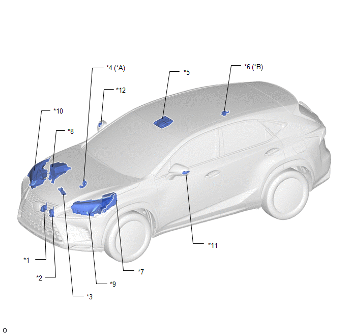
| *A | w/ Security Horn Assembly | *B | w/o Security Horn Assembly |
| *1 | HIGH PITCHED HORN ASSEMBLY | *2 | LOW PITCHED HORN ASSEMBLY |
| *3 | HOOD LOCK ASSEMBLY (ENGINE HOOD COURTESY SWITCH) | *4 | SECURITY HORN ASSEMBLY |
| *5 | MAP LIGHT ASSEMBLY | *6 | THEFT WARNING SIREN ASSEMBLY |
| *7 | NO. 1 ENGINE ROOM RELAY BLOCK AND JUNCTION BLOCK ASSEMBLY - AM2 FUSE - ECU-B NO.5 FUSE | *8 | NO. 2 ENGINE ROOM RELAY BLOCK AND JUNCTION BLOCK ASSEMBLY - ECU-B NO.1 FUSE - ECU-B NO.2 FUSE - HORN FUSE - HORN RELAY - SECURITY WARNING RELAY (w/ Security Horn Assembly) |
| *9 | HEADLIGHT ASSEMBLY LH | *10 | HEADLIGHT ASSEMBLY RH |
| *11 | SIDE TURN SIGNAL LIGHT ASSEMBLY LH | *12 | SIDE TURN SIGNAL LIGHT ASSEMBLY RH |
ILLUSTRATION
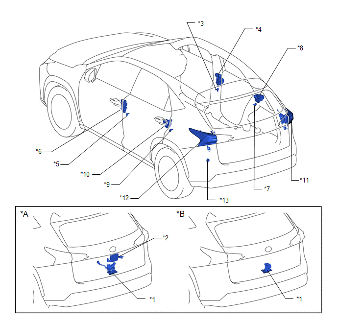
| *A | w/ Power Back Door System | *B | w/o Power Back Door System |
| *1 | BACK DOOR LOCK ASSEMBLY | *2 | MULTIPLEX NETWORK DOOR ECU |
| *3 | FRONT DOOR COURTESY LIGHT SWITCH ASSEMBLY RH | *4 | FRONT DOOR LOCK ASSEMBLY RH |
| *5 | FRONT DOOR COURTESY LIGHT SWITCH ASSEMBLY LH | *6 | FRONT DOOR LOCK ASSEMBLY LH |
| *7 | REAR DOOR COURTESY LIGHT SWITCH ASSEMBLY RH | *8 | REAR DOOR LOCK ASSEMBLY RH |
| *9 | REAR DOOR COURTESY LIGHT SWITCH ASSEMBLY LH | *10 | REAR DOOR LOCK ASSEMBLY LH |
| *11 | REAR COMBINATION LIGHT LENS AND BODY RH | *12 | REAR COMBINATION LIGHT LENS AND BODY LH |
| *13 | FUSE BLOCK ASSEMBLY - ECU-B NO.3 FUSE | - | - |
ILLUSTRATION
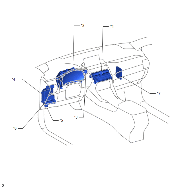
| *1 | AIR CONDITIONING CONTROL ASSEMBLY - SECURITY INDICATOR LIGHT | *2 | COMBINATION METER ASSEMBLY |
| *3 | POWER SWITCH | *4 | MAIN BODY ECU (MULTIPLEX NETWORK BODY ECU) |
| *5 | DLC3 | *6 | INSTRUMENT PANEL JUNCTION BLOCK ASSEMBLY - ACC FUSE - ECU-IG NO.2 FUSE |
| *7 | CERTIFICATION ECU (SMART KEY ECU ASSEMBLY) | - | - |
READ NEXT:
 System Description
SYSTEM DESCRIPTION
The theft deterrent system can be set/canceled by locking/unlocking the doors performing any of the following operation:
Entry lock/unlock operation
Wireless lock/unlock ope
How To Proceed With Troubleshooting
CAUTION / NOTICE / HINT HINT:
Use this procedure to troubleshoot the theft deterrent system.
*: Use the Techstream.
PROCEDURE 1. VEHICLE BROUGHT TO WORKSHOP
NEXT 2
Customize Parameters
CUSTOMIZE PARAMETERS INSTALL CUSTOMIZE THEFT DETERRENT SYSTEM HINT: The following items can be customized. NOTICE:
When the customer requests a change in a function, first make sure that the functi
SEE MORE:
Back Door Closer Operation Malfunction (B2250)
DESCRIPTION The multiplex network door ECU receives signals from the latch switch, initial switch, pawl switch and back door courtesy switch, which are built into the back door lock assembly. Based on these switch signals, the latch position of the back door lock assembly is determined. DTC No.
Lost Communication with Drive Motor Control Module "A" (U0110-160)
DESCRIPTION The MG ECU, which is built into in the inverter with converter assembly, controls motor (MG2) based on commands from the hybrid vehicle control ECU. The motor generator control ECU (MG ECU) monitors communication data and detects malfunctions. A communication error between the MG ECU and
