Lexus NX: Parts Location
Lexus NX Service Manual / Audio & Visual & Telematics / Park Assist / Monitoring / Parking Assist Monitor System / Parts Location
PARTS LOCATION
ILLUSTRATION
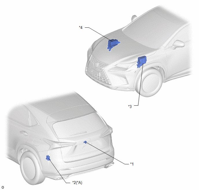
| *A | w/ Blind Spot Monitor System | - | - |
| *1 | REAR TELEVISION CAMERA ASSEMBLY | *2 | BLIND SPOT MONITOR SENSOR LH |
| *3 | ENGINE ROOM RELAY BLOCK - ECU-B NO.4 FUSE | *4 | NO. 2 ENGINE ROOM RELAY BLOCK - ECU-B NO.5 FUSE - ECU-IG NO.6 FUSE |
ILLUSTRATION
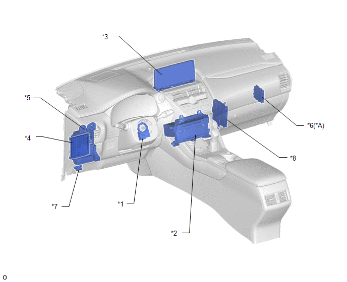
| *A | w/ Intuitive Parking Assist System | - | - |
| *1 | STEERING SENSOR | *2 | RADIO RECEIVER ASSEMBLY |
| *3 | MULTI-DISPLAY ASSEMBLY | *4 | MAIN BODY ECU (MULTIPLEX NETWORK BODY ECU) |
| *5 | INSTRUMENT PANEL JUNCTION BLOCK ASSEMBLY - ACC FUSE | *6 | CLEARANCE WARNING ECU ASSEMBLY |
| *7 | DLC3 | *8 | HYBRID VEHICLE CONTROL ECU |
READ NEXT:
 System Diagram
SYSTEM DIAGRAM Communication Table Sender Receiver Signal Line Radio Receiver Assembly Multi-display assembly Camera information signal GVIF Cable Radio Receiver Assembly Re
System Description
SYSTEM DESCRIPTION GENERAL (a) This system has a rear television camera assembly mounted on the back door to display an image of the area behind the vehicle on the display. The display panel also show
How To Proceed With Troubleshooting
CAUTION / NOTICE / HINT HINT:
Use the following procedure to troubleshoot the parking assist monitor system.
*: Use the Techstream.
PROCEDURE 1. VEHICLE BROUGHT TO WORKSHOP
NEXT
SEE MORE:
Removal
REMOVAL CAUTION / NOTICE / HINT HINT:
Use the same procedure for the RH and LH sides.
The procedure listed below is for the LH side.
PROCEDURE 1. PRECAUTION NOTICE: After the power switch off is turned off, there may be a waiting time before disconnecting the auxiliary negative (-) battery t
Problem Symptoms Table
PROBLEM SYMPTOMS TABLE NOTICE: When replacing the radio receiver assembly, always replace it with a new one. If a radio receiver assembly which was installed to another vehicle is used, the following may occur:
A communication malfunction DTC may be stored.
The radio receiver assembly may not o
© 2016-2026 Copyright www.lexunx.com
